Using spanning tree protocol (STP) to enhance layer-2 network topology maps

Active Publication Date: 2009-11-19
SOLARWINDS WORLDWIDE
View PDF7 Cites 43 Cited by
  • Summary
  • Abstract
  • Description
  • Claims
  • Application Information

AI Technical Summary

Benefits of technology

[0009]In response to these and other needs, embodiments of the present application relate to forming a topology mapping by forming an initial mapping of the topology of a network. Layer-2 address mapping tables are collected from the topology mapping. Spanning Tree Protocol (STP) data is then also collected, along with address translatio

Problems solved by technology

These invalidated entries correspond to Layer-2 addresses downstream from the switch-to-s

Method used


Image

  • Using spanning tree protocol (STP) to enhance layer-2 network topology maps
  • Using spanning tree protocol (STP) to enhance layer-2 network topology maps
  • Using spanning tree protocol (STP) to enhance layer-2 network topology maps

Examples


Embodiment Construction

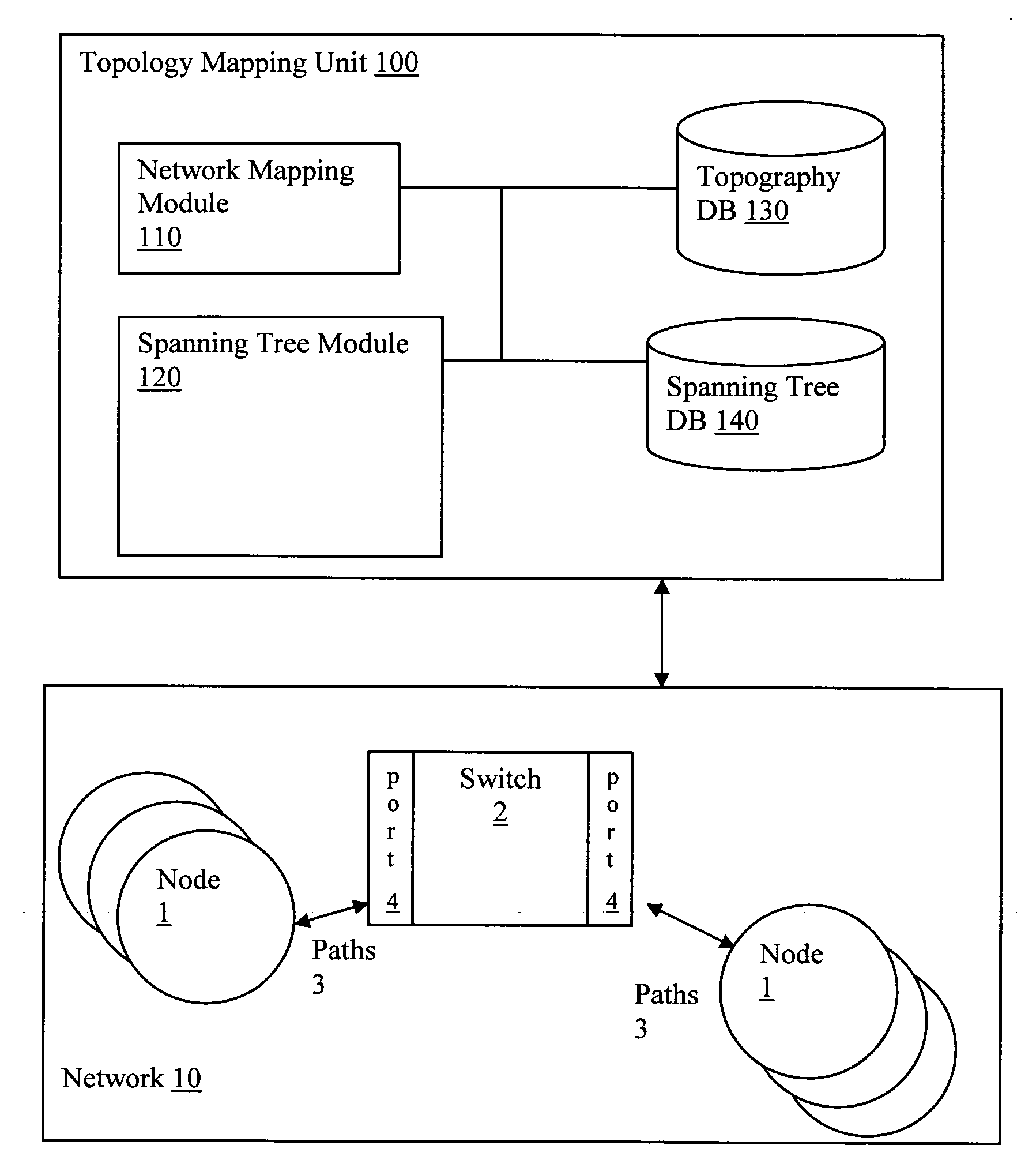
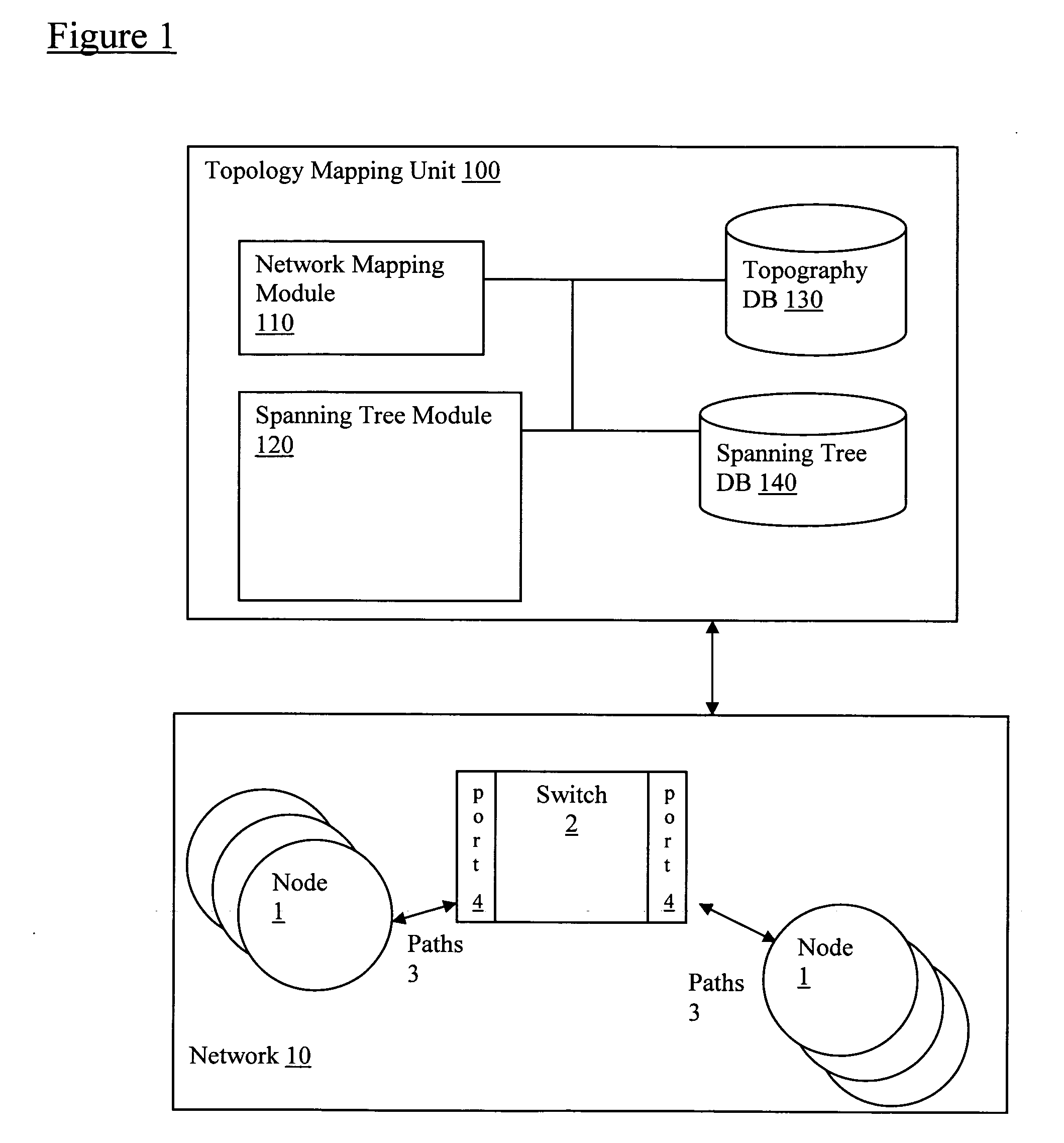
[0017]Referring to FIG. 1, embodiments of the present application relate to a topology mapping unit 100 configured to connect to network 10 that includes, for example, multiple nodes 1, switches 2 with multiple ports 4, and paths 3.

[0018]The topology mapping unit 100 includes a mapping module 110. In particular, the mapping module 110 is configured to map components in the network 10. Various network topography mapping techniques are known and may be integrated within the embodiments of the present application, as described in greater detail below.

[0019]The mapping module 110 automatically discovers everything on the network, including desktops, servers, printers, switches and routers using identification and discovery methods (ping / ICMP, SNMP, SIP-based VoIP, NetBIOS and more) to scan IP address ranges and find nodes, as described below in FIG. 2.

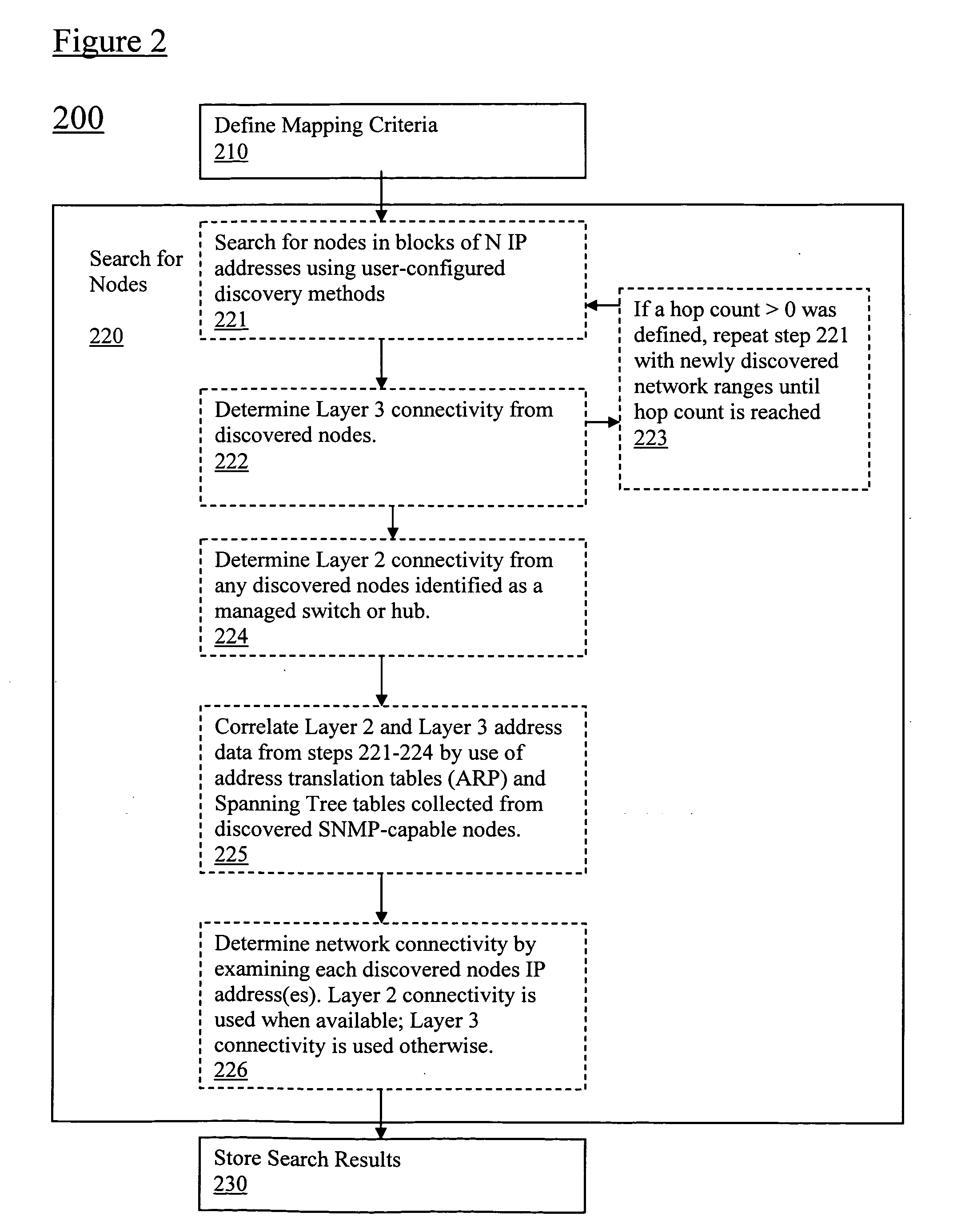
[0020]Referring now to FIG. 2, a mapping method 200 in accordance with embodiments of the present application is provided. In particular,...


PUM


Abstract

Spanning Tree Protocol (STP) data is obtained via network switch (SNMP) queries to enhance identification of switch-to-switch links in Layer-2 mapping. In particular, by analyzing the STP data, ambiguity in determining switch uplink ports may be reduced. Specifically, the STP data can be used in conjunction with other topography data to provide Layer-2 connectivity for nodes on a network topology. Layer-2 address mapping tables are collected from a topology mapping, and STP data is collected, along with address translation tables (ARP) tables. Using this information, switches are identified using Layer-2 address tables. The STP data can be correlated by comparing data in switches, identifying switch ports directly connected to other switch ports, and eliminating direct switch-to-switch port connections from consideration for further Layer-2 node mappings.

Description

FIELD OF THE INVENTION[0001]Spaning Tree Protocol (STP) data obtained via network switch (SNMP) queries may be used to enhance identification of switch-to-switch links in Layer-2 mapping. In particular, by analyzing the STP data, ambiguity in determining switch uplink ports may be reduced. Specifically, the STP data can be used in conjunction with other data to provide Layer-2 connectivity for nodes on a network topology.BACKGROUND OF THE INVENTION[0002]Network topology is the study of the arrangement or mapping of the elements (links, nodes, etc.) of a network, especially the physical (real) and logical (virtual) interconnections between nodes. A local area network (LAN) is one example of a network that exhibits both a physical topology and a logical topology. Any given node in the LAN will have one or more links to one or more other nodes in the network and the mapping of these links and nodes onto a graph results in a geometrical shape that determines the physical topology of the...

Claims


Application Information

Patent Timeline
IPC IPC(8): H04L12/28H04L45/02H04L45/18
CPCH04L41/0213H04L41/12H04L45/66H04L45/18H04L45/48H04L45/02
Inventor SWAN, MICHAEL JON
Owner SOLARWINDS WORLDWIDE
Why Eureka
Try Eureka