Multi-mount

a multi-mount and mount technology, applied in the field of multi-mount, can solve the problems of increasing the weight of the firearm, limited space on the 1913 rail, and inability to carry a firearm at night time, so as to facilitate removable securing, save weight, and add weight to the firearm

Inactive Publication Date: 2009-11-26
KISER JOSEPH K
View PDF8 Cites 17 Cited by
  • Summary
  • Abstract
  • Description
  • Claims
  • Application Information

AI Technical Summary

Problems solved by technology

Night time operations and long range operations are not practical with most conventional non magnified electronic sights or night visions scopes.
Utilizing one mount for the non magnified electronic optic and another for either the magnifying or night vision device creates several issues.
This is required because the amount of space on the 1913 rail is limited.
The use of two mounts increases the weight of the firearm and also forces the user to store both the mount and optic when not in use.
Because of the offset required to place the secondary optic in the proper orientation with the primary optic the secondary optic with attached mount presents an awkward package for the user to stow in a place which is also convenient to access should the need for the secondary optic present itself.
Limited 1913 Picatinny rail space is being utilized by the addition of a secondary mount thus limiting the users' options for primary optic placement.
None of these mounts and various modifications provide a single mount which has a means to attach the primary optic and also provides a base of proper height for optics which are deigned to be used in conjunction with the primary optic.
This additional mount in order to save weight is often offset from its base creating a cumbersome package for the user to stow while not in use.
This additional mount also adds weight to the firearm and limits the positions which the user may mount the primary electronic gun site.

Method used


Image

  • Multi-mount
  • Multi-mount
  • Multi-mount

Examples


Embodiment Construction

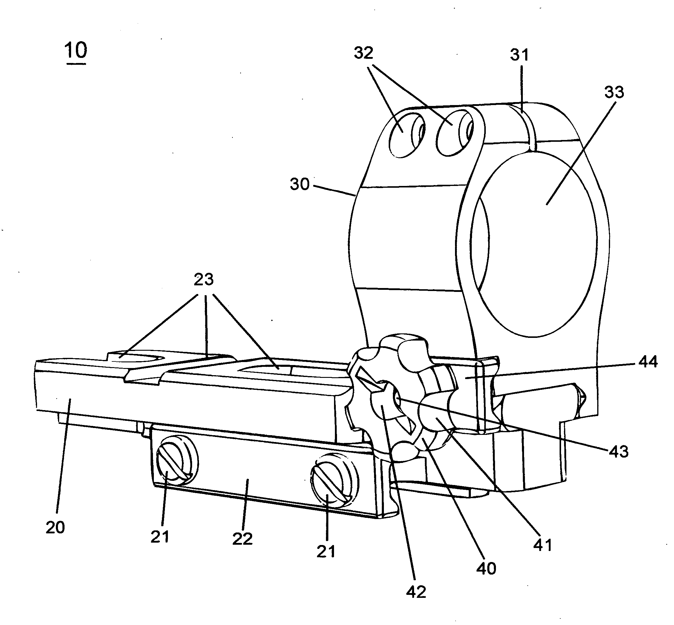
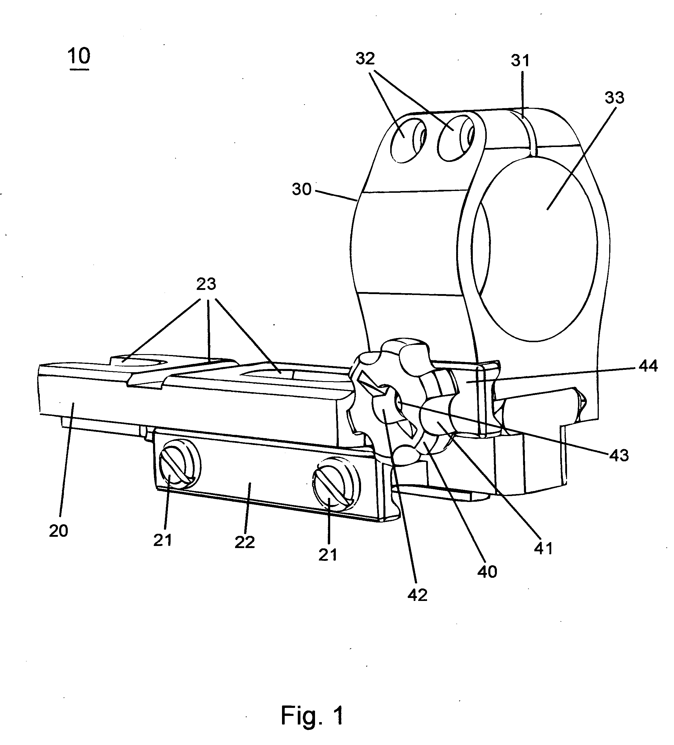
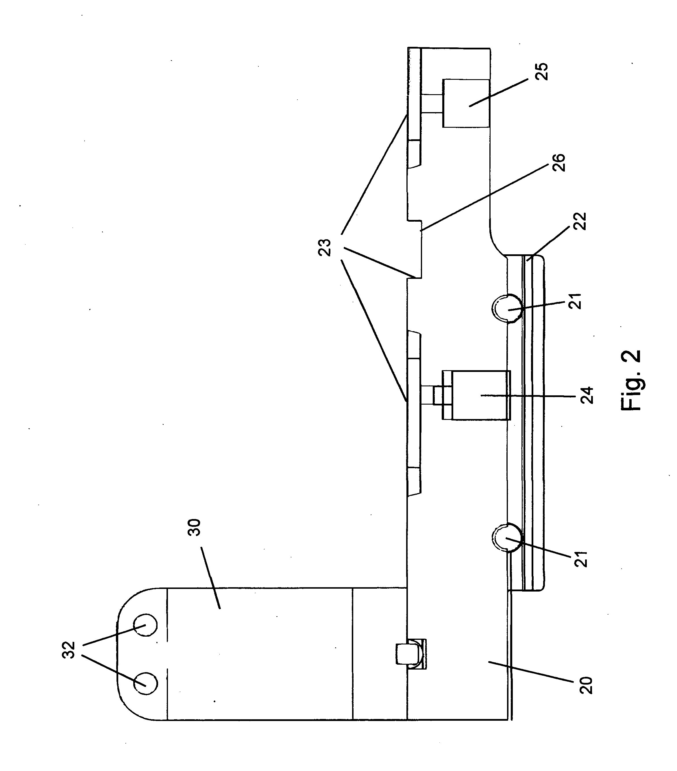
[0023]Referring to the drawings in detail wherein like elements are indicated by like numerals, there is shown in FIG. 1, perspective side view of the proposed multi mount 10. The main components are the base 20, and the secondary optic ring 30. The base 20 is design to interface with a 1913 spec Picatinny rail, well known in the prior art. There are two screws 21, and a retaining plate 22 which hold the base 20 onto a Picatinny rail.

[0024]The secondary optic ring 30 is retained onto the base 20 by means of a retention knob 40 which places pressure on a retention plate 44, when the retention knob 40 is threadedly secured to a screw 43 which runs transverse to the axis of the base 20.

[0025]The secondary optic ring 30 has a gap machined into the top portion of the ring 30. Two retention screws 32 are threaded into the aluminum housing and when tightened to close the gap 31 on the secondary optic ring 30. A 30 mm void 33 for an optic is provided on the secondary optic ring 30. The appr...


PUM


Abstract

A sight mount for a firearm includes a base, and a rearwardly extending mounting portion for supporting a removable secondary optic mount. The base includes dovetail rails for securing the base to a firearm, and a mount position for accepting an electronic optic. The rearwardly extending mounting portion has transverse slots which follow the 1913 Picatinny specifications. The base serves as a mount point for up to two optics, the primary and secondary optics. The primary optic being a non magnified electronic optic and the secondary optic such either a night vision device or magnifier. The extended mounting position utilizes a small, light weight ring or other apparatus as is appropriate to hold onto the secondary optic. By using one base for both optics weight is reduced and the secondary optic when remove provides a stream lined package.

Description

BACKGROUND OF THE INVENTION[0001]1. Field of Invention[0002]The present invention relates to optical mounts for a firearm and, more particularly, to optical mounts for firearms which allow for combination of multiple electronic sights and accessories to improve the operational capability of the host rifle.[0003]2. Prior Art[0004]The use of electronic guns sights, magnifying devices and night vision is proliferating in military, law enforcement and civilian circles. The use of a non magnified optic is very popular for users who are operating in a home environment where the engagement range is very short. Night time operations and long range operations are not practical with most conventional non magnified electronic sights or night visions scopes. As such mounting either a magnifying device or night vision optic behind the primary electronic aiming device has become common place. Traditionally the use of various mounts which will fit behind the optic has been the solution. The majori...

Claims


Application Information

Patent Timeline
Patent Type & Authority Applications(United States)
IPC IPC(8): F41G1/38
CPCF41G1/01F41G11/003F41G1/387
Inventor KISER, JOSEPH K.
Owner KISER JOSEPH K
Why Eureka
Try Eureka