Mixing tube for a waterjet system

a technology of waterjet system and mixing tube, which is applied in the direction of abrasive equipment, metal working equipment, manufacturing tools, etc., can solve the problems of increasing manufacturing costs, difficult to remove the collet, and loss of accurate positioning of the mixing tube tip

Active Publication Date: 2009-11-26
FLOW INT
View PDF15 Cites 48 Cited by
  • Summary
  • Abstract
  • Description
  • Claims
  • Application Information

AI Technical Summary

Problems solved by technology

High torques may be applied to these mechanical components which may require manual operation and result in losing accurate positioning of the mixing tube tip.
If the cutting head assembly has a collet, a tapered surface must be precisely machined into the cutting head body to accommodate the collet, further increasing manufacturing costs.
It may be difficult to remove the collet because the collet and the cutting head body may lock together, especially when the tapered surfaces of the cutting head body react significant forces (e.g., clamp-up forces).
When the fluid jet passes through the mixing tube at a high velocity, the mixing tube, even if made of a highly wear-resistant material, experiences appreciable wear along its interior cylindrical surface surrounding the fluid jet.
Frequent replacement of worn mixing tubes often leads to problems attributable to the way the mixing tube is retained in the cutting head body, resulting in impaired performance of the system.
Corrosion of the cutting head assembly may also impair performance.
Components for retaining the mixing tube, for example, are often made of a material susceptible to corrosion, and have to be frequently replaced if exposed to corrosive materials for significant amounts of time.
Replacing corroded components often causes damage to other components of the cutting head requiring replacement of non-corroded components.
Water is one corrosive material that may lead to rusting of such components.
Rust-resistant components, such as collets made entirely of stainless steel, are relatively expensive.
To replace the mixing tube, the seal disengages a cartridge housing of the cartridge assembly and may therefore result in contamination of the seal and the cartridge housing.
This contamination can lead to leakage during operation of the waterjet system.

Method used


Image

  • Mixing tube for a waterjet system
  • Mixing tube for a waterjet system
  • Mixing tube for a waterjet system

Examples


Embodiment Construction

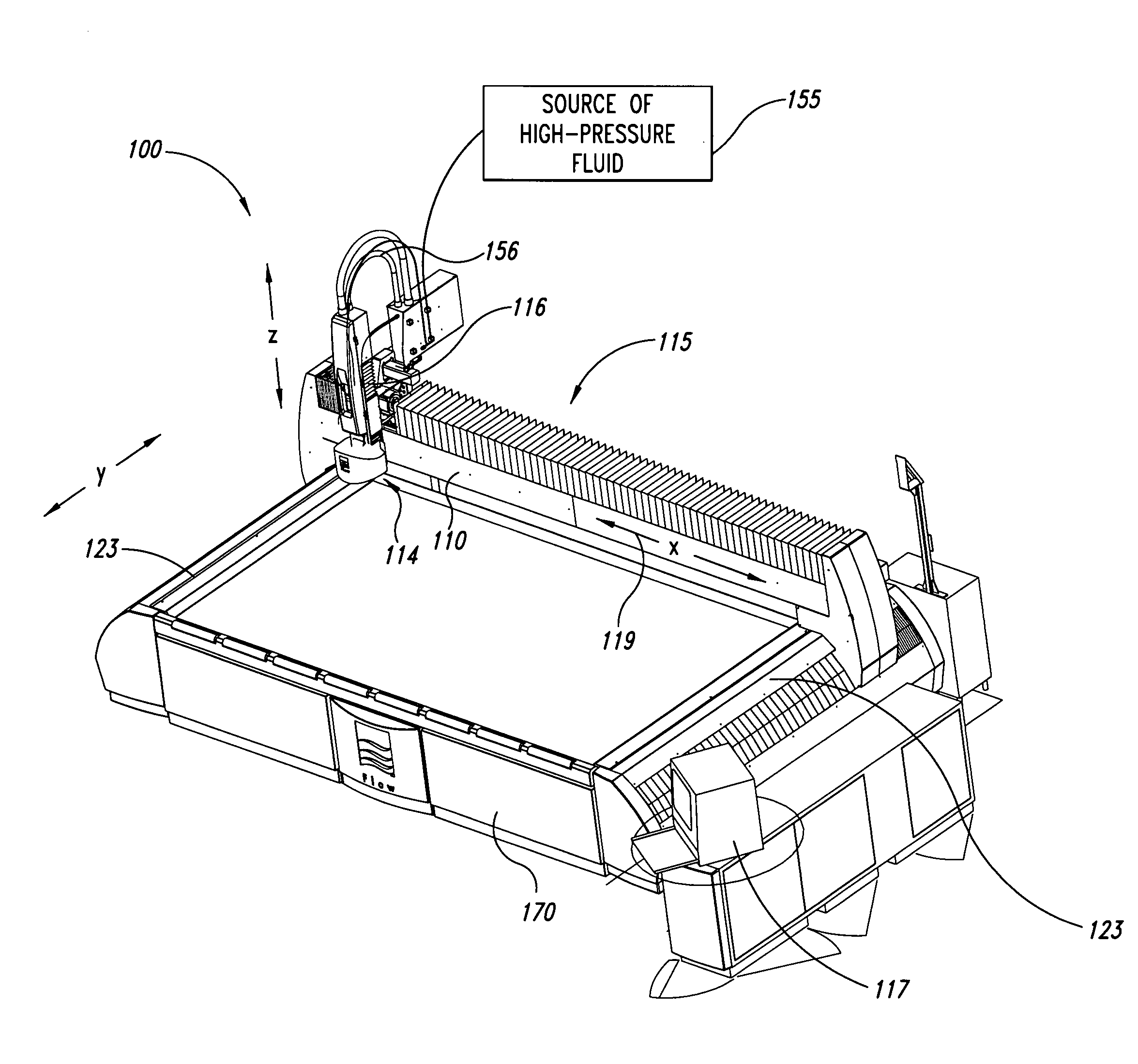
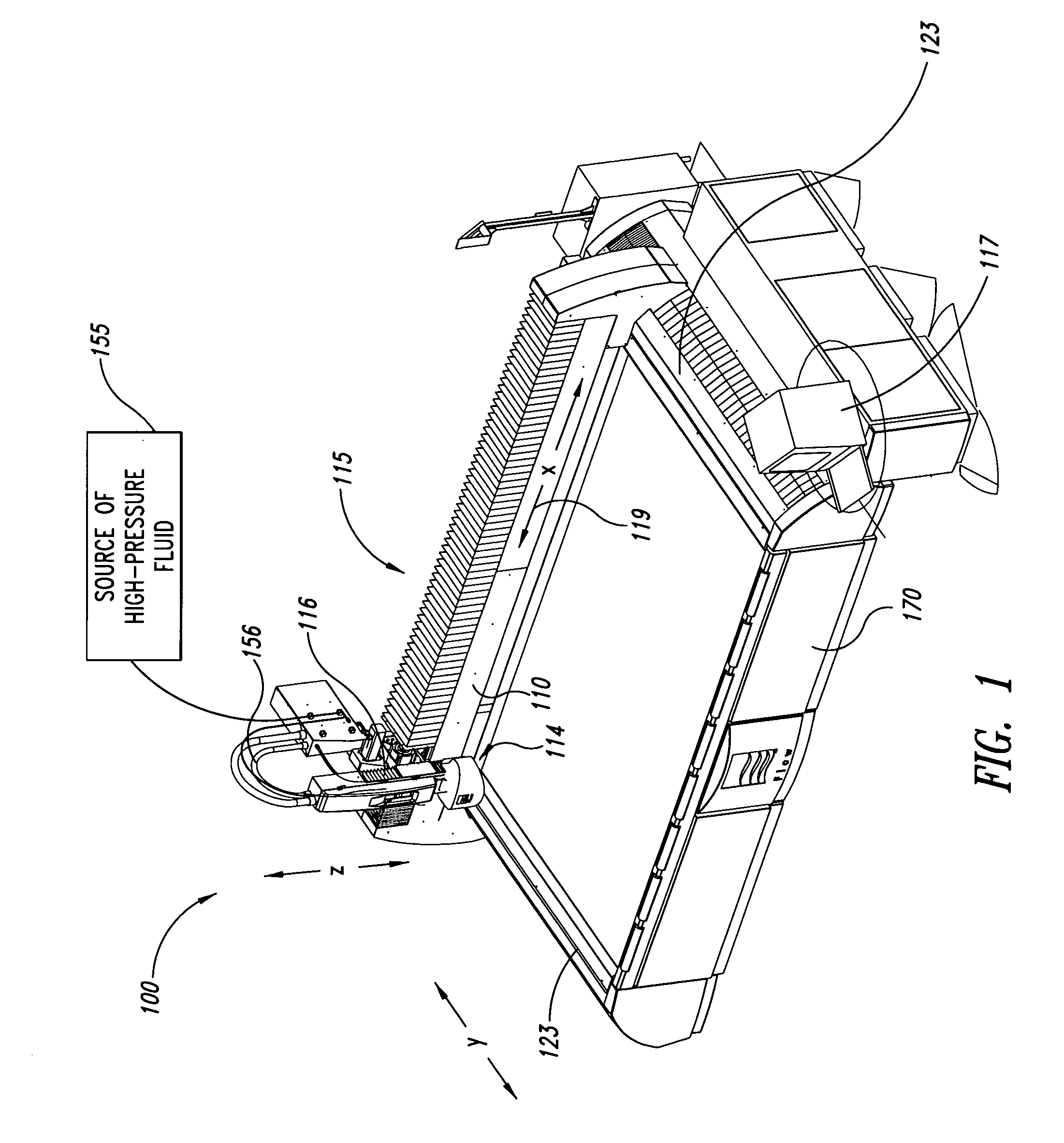
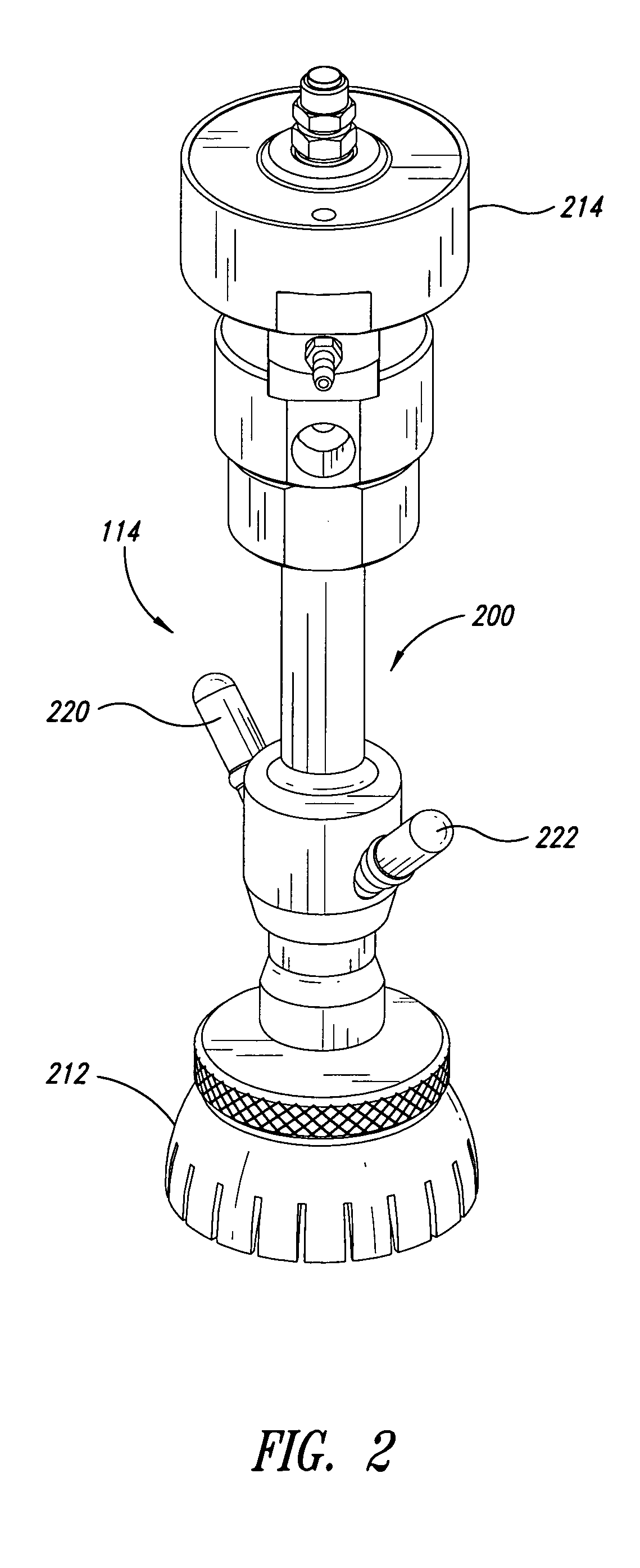
[0031]The following description relates to systems for generating and delivering fluid jets suitable for cleaning, abrading, cutting, milling, or otherwise processing workpieces. A waterjet system can have a cutting head assembly with a quick release mixing tube. The mixing tube can be conveniently installed and removed without utilizing torquing tools, such as wrenches, that may damage the waterjet system. The mixing tube can be releasably retained in a cutting head body of the cutting head assembly via magnetic attraction. For example, the mixing tube can be biased towards the cutting head body to reduce, limit, or substantially prevent unwanted movement of the mixing tube relative to the cutting head body. One or more magnets can produce magnetic forces that keep the mixing tube retained in the cutting head body. An operator can conveniently pull the mixing tube out of the cutting head body, and another mixing tube can then be installed in the cutting head body. This process can ...


PUM

PropertyMeasurementUnit
pressuresaaaaaaaaaa
pressureaaaaaaaaaa
pressureaaaaaaaaaa

Abstract

A waterjet system for generating and delivering fluid jets suitable for processing a workpiece has a cutting head body and a mixing tube. The cutting head body includes a mixing chamber and a bore. The bore is positioned downstream of the mixing chamber, and an abrasive fluid jet from the mixing chamber passes through the mixing tube. The mixing tube has a first coupler adapted to magnetically couple the mixing tube to the cutting head body when the mixing tube is installed. The cutting head body has a second coupler positioned to engage the first coupler of the mixing tube to keep the mixing tube properly positioned during operation of the waterjet system.

Description

BACKGROUND[0001]1. Technical Field[0002]The present invention relates generally to waterjet systems and, in particular, to abrasive waterjet systems having a magnetically retained mixing tube.[0003]2. Description of the Related Art[0004]Conventional waterjet systems are used to process workpieces by pressurizing fluid and then delivering the pressurized fluid against a workpiece. Abrasive waterjet systems produce high-pressure abrasive fluid jets suitable for cutting through hard materials. High-pressure fluid can flow through a jewel orifice in a cutting head assembly to form a high-pressure fluid jet into which abrasive particles are entrained. This entrainment can take place within a chamber of the cutting head assembly. The high-pressure abrasive fluid jet passes through a mixing tube and is discharged from the mixing tube towards the workpiece.[0005]The axis of the mixing tube has to be aligned with the waterjet coming out of the jewel orifice such that the abrasive fluid jet i...

Claims


Application Information

Patent Timeline
Patent Type & Authority Applications(United States)
IPC IPC(8): B26D3/00B05B9/00B23P11/00
CPCB24C1/045Y10T29/49826B24C5/02Y10T83/0591
Inventor HASHISH, MOHAMED
Owner FLOW INT
Why Eureka
Try Eureka