
System, method, and computer software code for linking a plurality of powered systems having different linking protocols to operate as a single powered system

Inactive Publication Date: 2009-11-26
GENERAL ELECTRIC CO
View PDF12 Cites 7 Cited by
  • Summary
  • Abstract
  • Description
  • Claims
  • Application Information

AI Technical Summary

Benefits of technology

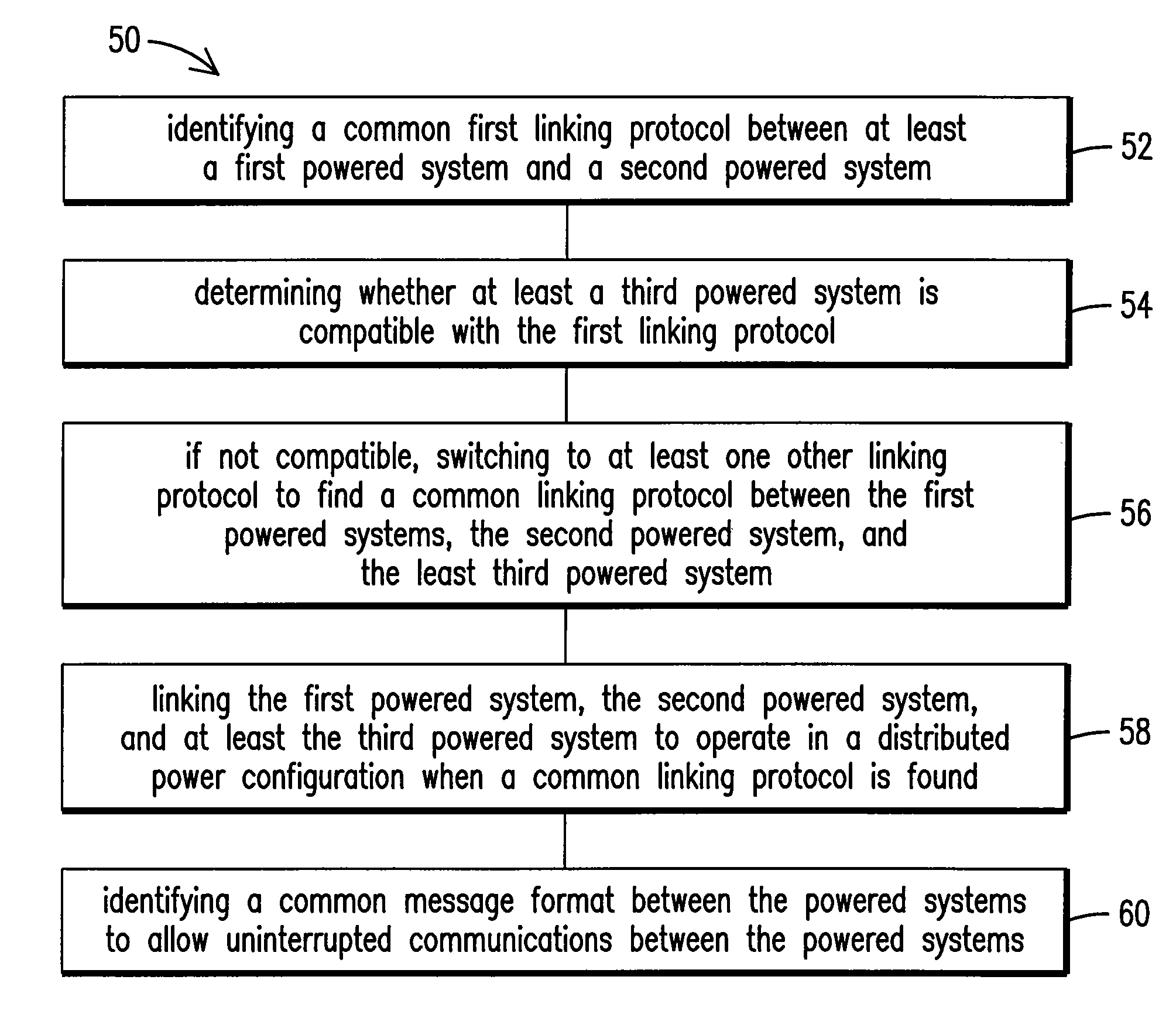
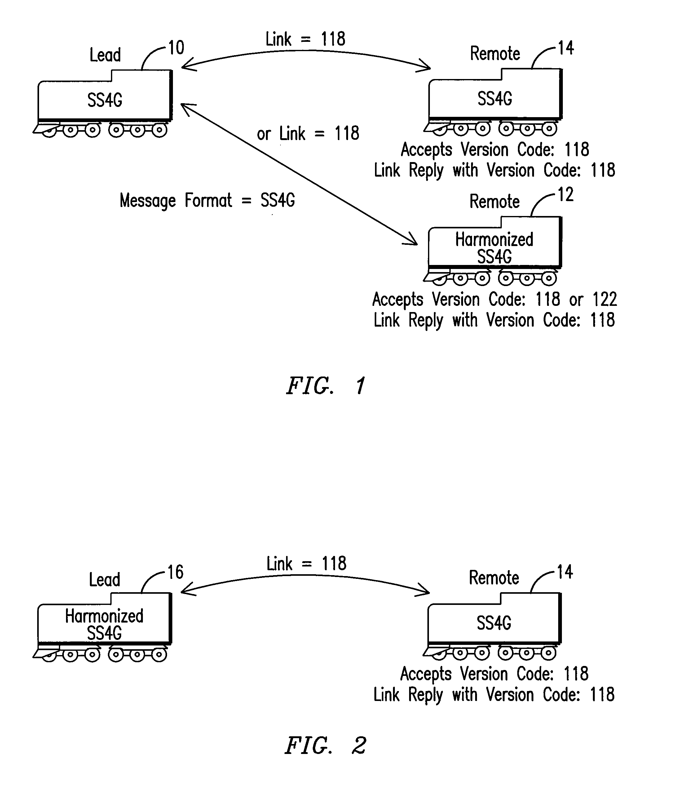
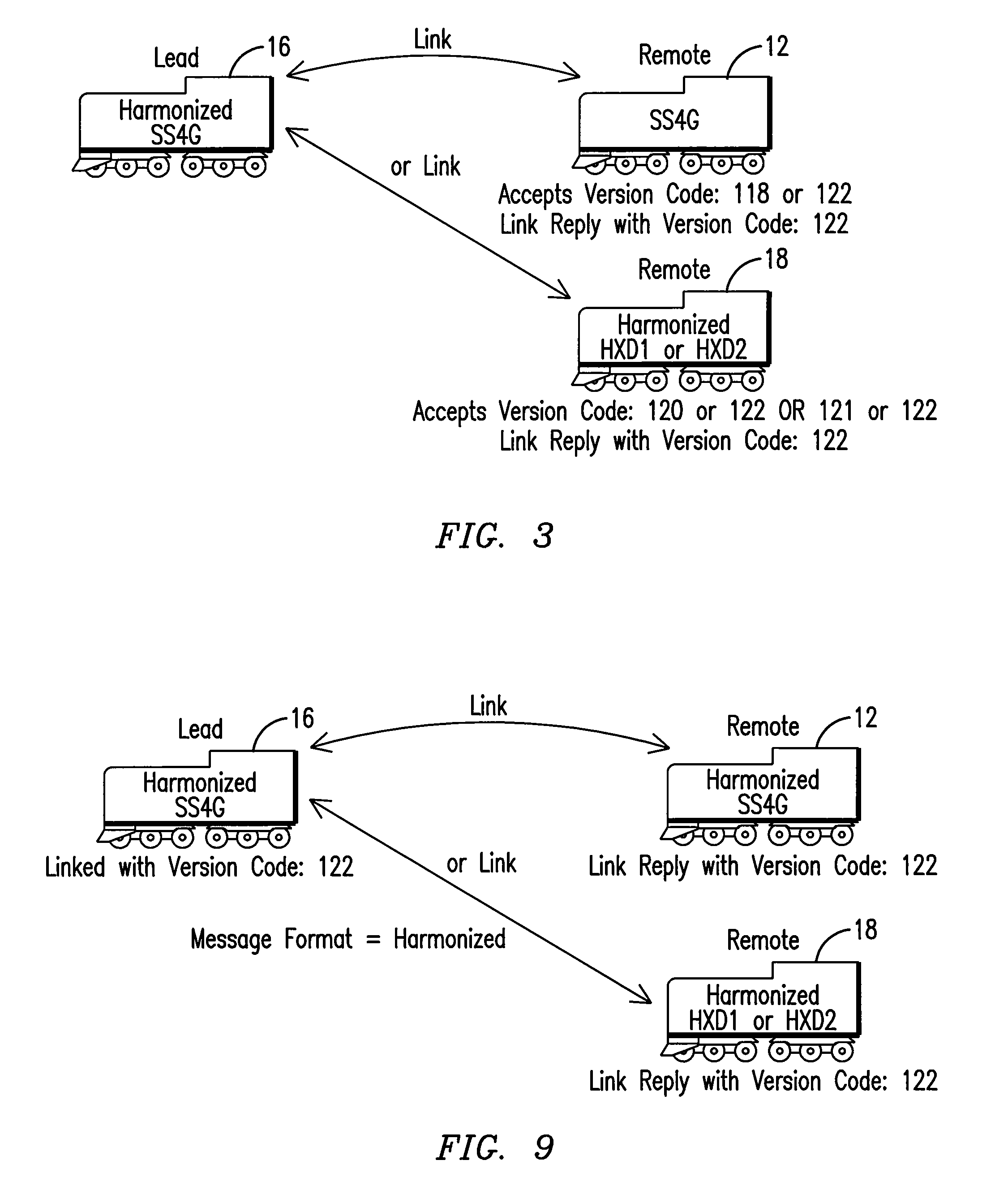
[0008]Embodiments of the present invention relate to a system, method, and a computer software code for linking together three (or more) powered systems to operate as a single distributed power system. In one aspect, the method includes identifying a first linking protocol between at least a first powered system and a second powered system. A determination is made whether at least a third powered system is compatible with the first linking protocol. If the third powered system is not compatible with the first linking protocol, the method further comprises switching to at least a second linking protocol to find a common linking protocol between the first powered system, the second powered system, and the at least third pow

Problems solved by technology

Due to scheduling constraints, owners and operators of locomotives may have a limited timeframe to perform the upgrades.
Also, when it is desirable to include additional locomotive types that must operate together in the same train, reworking existing DP control systems becomes cost prohibitive, since such changes require significant more time to accomplish establishing a workable linking scheme between three or more different types of DP control systems.

Method used


Image

  • System, method, and computer software code for linking a plurality of powered systems having different linking protocols to operate as a single powered system
  • System, method, and computer software code for linking a plurality of powered systems having different linking protocols to operate as a single powered system
  • System, method, and computer software code for linking a plurality of powered systems having different linking protocols to operate as a single powered system

Examples


Embodiment Construction

[0023]Though exemplary embodiments of the present invention are described with respect to rail vehicles or railway transportation systems, specifically trains and locomotives, exemplary embodiments of the invention are also applicable for other powered systems as well, such as but not limited to off-highway vehicles, marine vessels, stationary units, agricultural vehicles, and transport buses, where either multiple vehicles or vessels, and / or multiple engines, are operated together. With respect to railway, marine, transport vehicles, agricultural vehicles, or off-highway vehicles this may refer to the movement of any of these powered systems from a present location to a destination. In the case of stationary applications, such as but not limited to a stationary power generating station or network of power generating stations, operation may refer to an amount of wattage (e.g., MW / hr) or other parameter or requirement to be satisfied by the powered system.

[0024]More specifically, alt...


PUM


Abstract

A method for linking together three or more powered systems to operate as a single distributed power system, the method includes identifying a first linking protocol between at least a first powered system and a second powered system, determining whether at least a third powered system is compatible with the first linking protocol, if not compatible, switching to at least a second linking protocol to find a common linking protocol between the first powered system, the second powered system, and at least the third powered system, and linking the first powered system, the second powered system, and at least the third power system to operate in a distributed power configuration when the common linking protocol is found. A system and a computer software code linking together two or more powered systems to operate as a single distributed power system are also disclosed.

Description

CROSS-REFERENCE TO RELATED APPLICATIONS[0001]This application claims the benefit of U.S. Provisional Application No. 61 / 056,062 filed May 26, 2008, and incorporated herein by reference in its entirety.BACKGROUND OF THE INVENTION[0002]This invention relates generally to communication systems and, more particularly, to the distributed power control of two or more powered systems.[0003]Trains are commonly used as an efficient means for hauling cargo and / or passengers over long distances. A typical train includes a plurality of non-powered rail cars and a plurality of locomotives for moving the non-powered rail cars over a track. Two or more locomotives grouped or otherwise controlled together for traction purposes are commonly referred to as a “consist.” Distributed power control systems (hereinafter distributed power, or DP systems, or simply DP) allow for the operation of one or more remote locomotives (or group of locomotives forming a consist) in a train. The remote locomotive(s) a...

Claims


Application Information

Patent Timeline
IPC IPC(8): G06F17/00
CPCB60L15/42B61L15/0027H02J3/38B60L2200/26H04L69/24Y04S10/126Y02E60/721H04L69/18Y02E60/00
Inventor SMITH, EUGENE A.WHEELER, MARK WAYNEWALDO, LAWRENCE R.RATNESAR, RABI N.KELLEY, JAMES
Owner GENERAL ELECTRIC CO
Learn More