
Directional RFID reader

a directional rfid and reader technology, applied in the field of system control data, can solve the problems of limited computer resources in these environments, inconvenient use of terminals in certain environments, and still large in siz

Inactive Publication Date: 2009-12-03
PATIENTSAFE SOLUTIONS
View PDF106 Cites 74 Cited by
  • Summary
  • Abstract
  • Description
  • Claims
  • Application Information

AI Technical Summary

Benefits of technology

[0009]In some embodiments the hand held device further comprises a database of identification information. In some embodiments the hand held device further comprises an aiming light. In some embodiments the animal is a human. In some embodiments the hand held device is configured to display identification information on the hand held. In some embodiments the identification information is at least one of a number and a name. In some embodiments the RFID tag is attached to the animal by at least one of a bracelet, a necklace, a collar, and a pin.
[0010]In another embodiment at method for monitoring workflow in a medical environment comprises providing a hand held device comprising a directional antenna coupled to an RFID reader, providing an RFID tag and reading the RFID tag with the hand held device.
[0011]In some embodiments the directional antenna comprises a material selected from the group consisting of ferrite, titanium and ceramic. In some embodiments the RFID tag comprises as least one of a bracelet, a necklace, a collar, and a pin. In some embodiments the hand held device is configured to visually signal whether the RFID tag has been read.
[0012]In some embodiments the method further comprises providing an aiming light coupled to the hand held and aligning the directional antenna with

Problems solved by technology

Computer resources in these environments are limited due to inadequate availability of access points such as input / output (I / O) stations or terminals.
Although stationary terminals have a large screen, familiar full-featured keyboard, and mouse input devices, such terminals are inconvenient to use in certain environments due to lack of portability, or availability due to cost and space constraints.
However, they are still somewhat large in size, bulky to transport, have limited battery life, require two hands to operate, and are expensive.
Such devices are often costly and require two-handed use for operation.
Further, such devices may require time consuming tasks in operation that slow down medical workflow.

Method used


Image

  • Directional RFID reader
  • Directional RFID reader
  • Directional RFID reader

Examples


example process

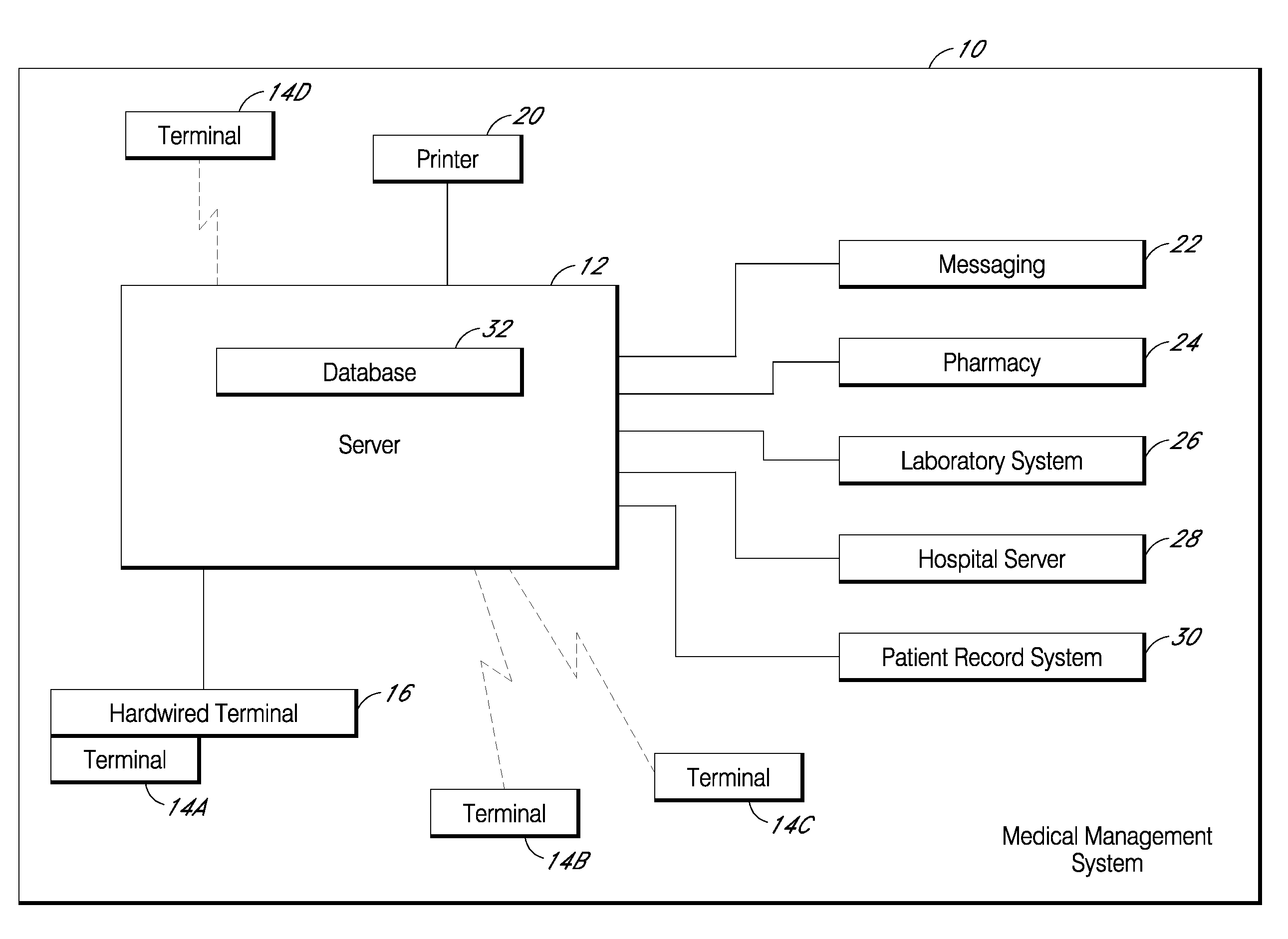
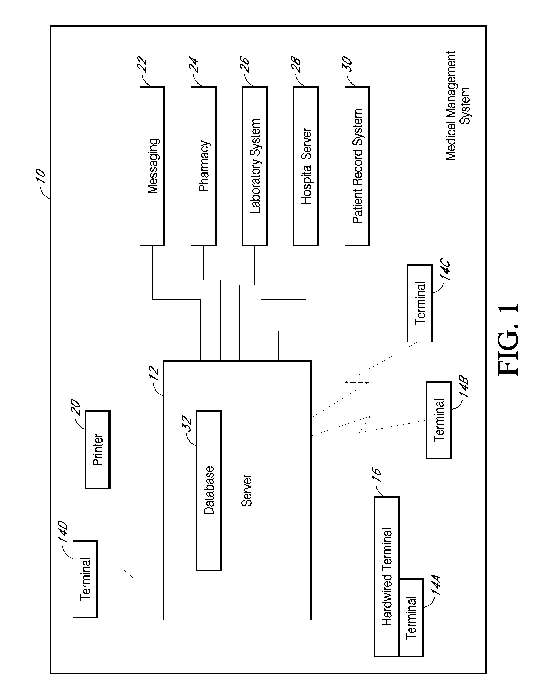
[0128]FIG. 12 is an example of a Medication Worksheet 1200 that may be used in conjunction with a terminal 14 and server 12, operating in a system such as the hospital system 10 of FIG. 1, and using, for example, the processes of FIGS. 6-11. In one embodiment, a user such as a nurse, authorized personnel, or system administrator obtains a printed version of the Medication Worksheet 1200 at the beginning of a working shift. For example, as previously discussed, the user of a terminal 14 may scan a code corresponding to an instruction to print a Medication Worksheet, and then scan a code corresponding to data identifying the user. In response to the instruction, the server 12 would facilitate printing of the Medication Worksheet for the identified user.

[0129]The Medication Worksheet 1200 comprises a number of fields supplying a variety of information. For example, the Medication Worksheet 1200 can include an assignment field 1210 that identifies the responsible user or nurse, applicab...


PUM


Abstract

One embodiment is a hand held device, which comprises a body comprising a directional antenna and an integrated radio frequency identification (“RFID”) reader coupled to the directional antenna. Another embodiment provides a system and a method for identifying an animal, which comprises an RFID tag attached to the animal and a hand held device, wherein the hand held device comprises an RFID reader and a directional antenna coupled to the RFID reader.

Description

BACKGROUND OF THE INVENTION[0001]1. Field of the Invention[0002]This invention relates generally to a system for controlling data in a health care environment. More particularly, this invention relates to a medical processing system that includes a handheld scanner for patient identification and for entering commands and data into a medical management system.[0003]2. Description of the Related Art[0004]An effective medical computer system allows for a large number of simultaneous users. Some computer tasks in a medical environment require a high degree of mobility, ease of operation and low cost implementation. One example of such tasks is the administration and documentation of care provided to patients in a medical or hospital environment. Computer resources in these environments are limited due to inadequate availability of access points such as input / output (I / O) stations or terminals. Although stationary terminals have a large screen, familiar full-featured keyboard, and mouse ...

Claims


Application Information

Patent Timeline
IPC IPC(8): H04Q5/22
CPCG06F19/323G06F19/327G06F19/3462G06K2207/1011G06K7/0008G06K7/10079G06K7/10386G06K7/0004G16H10/60G16H10/65G16H40/20
Inventor ROOF, WILLIAM H.
Owner PATIENTSAFE SOLUTIONS
Learn More