Eureka AIR delivers breakthrough ideas for toughest innovation challenges, trusted by R&D personnel around the world.

LED lighting fixture

Active Publication Date: 2009-12-03
IDEAL IND LIGHTING LLC
View PDF66 Cites 20 Cited by
  • Summary
  • Abstract
  • Description
  • Claims
  • Application Information

AI Technical Summary

Benefits of technology

[0008]Another object of the invention is to provide an improved LED lighting fixture that is readily adaptable for a variety of mounting positions and situations.
[0009]Another object of the invention is to provide an improved outdoor LED lighting fixture with excellent protection of the electronic LED drivers needed for such products.
[0010]Still another object of the invention is to provide an improved LED lighting fixture with both good protection of electronic LED drivers and excellent heat dissipation.
[0031]In such embodiments, the post may have a height from few inches to several feet. For example, the few-inch post allows mounting of the fixture with the upright lower portion adjacent to the mounting surface. In another example, the post may be about two and a half feet such that the inventive fixture is at a level of a typical bollard light. The positioning of LEDs for emitting light in downwardly coupled with the LED optics provides a greater amount of luminance in a desired direction. Such greater luminance is achieved by avoiding loss of light that occurs in typical bollards which use reflectors to redirecting light from the inside of a cylindrical bollard housing. Yet in another example of a post-top lighting fixture in accordance with the present invention the post may be about eight-feet high. Such post-top fixtures may be positioned to illuminate walking paths, sidewalks or the like.

Problems solved by technology

High-luminance light fixtures using LEDs as light source for outdoor applications present particularly challenging problems.
High costs due to high complexity becomes a particularly difficult problem when high luminance, reliability, and durability are essential to product success.
Keeping electronic LED drivers in a water / air-tight location may also be problematic, particularly when the light fixtures are constantly exposed to the elements and many LEDs are used.
Yet another challenge is the problem of achieving a high level of adaptability in order to meet a wide variety of different luminance requirements and satisfy a vide variety of applications.
That is, providing a fixture which can be adapted to give significantly greater or lesser amounts of luminance in a desired direction as deemed appropriate for particular applications is a difficult problem.
Dealing with heat dissipation requirements is still another problem area for high-luminance LED light fixtures.
Heal dissipation is difficult in part because high-luminance LED light fixtures typically have many LEDs.
Complex structures for module mounting and heat dissipation have sometimes been deemed necessary, and all of this adds to complexity and cost.

Method used


Image

  • LED lighting fixture
  • LED lighting fixture
  • LED lighting fixture

Examples


Embodiment Construction

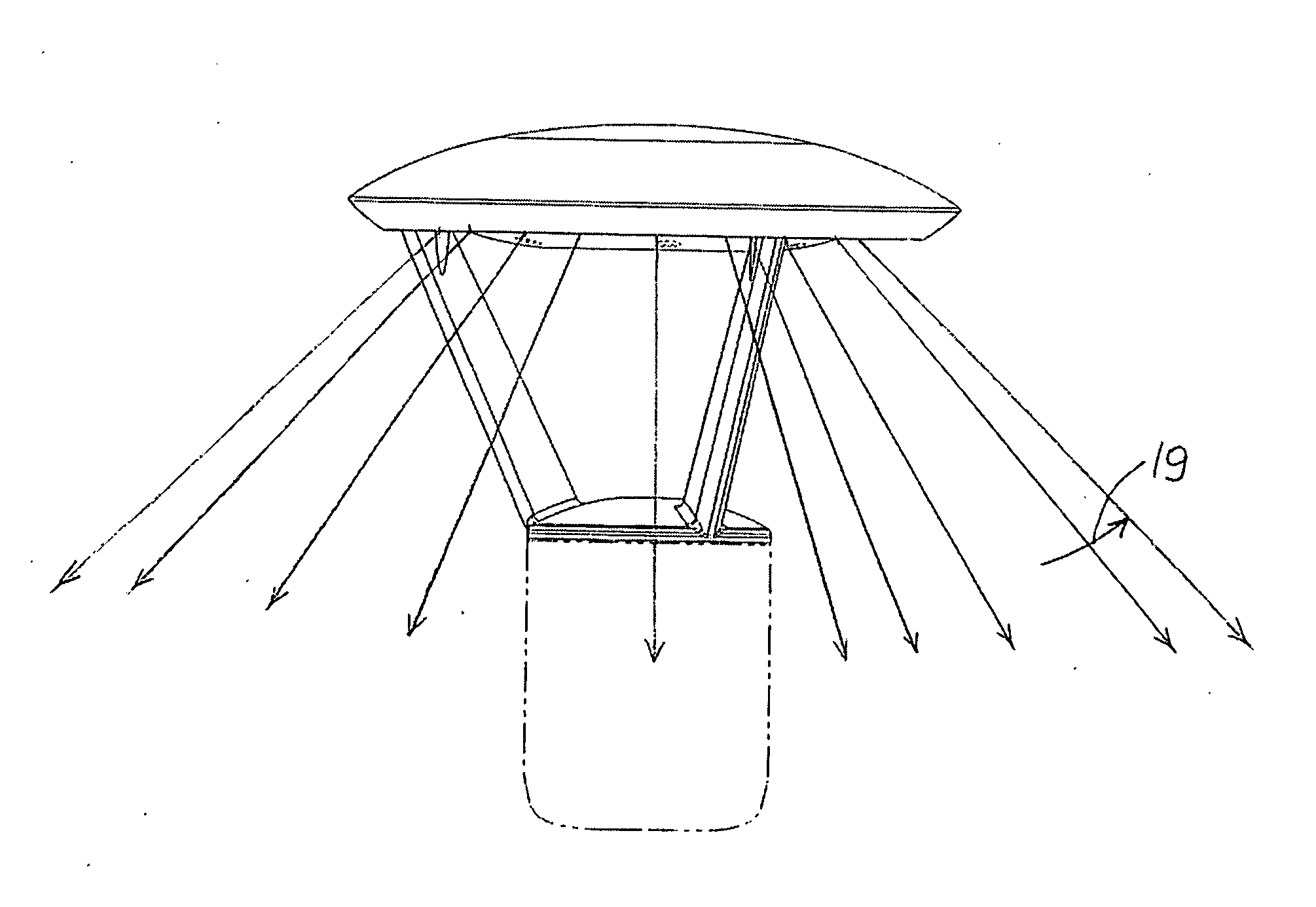
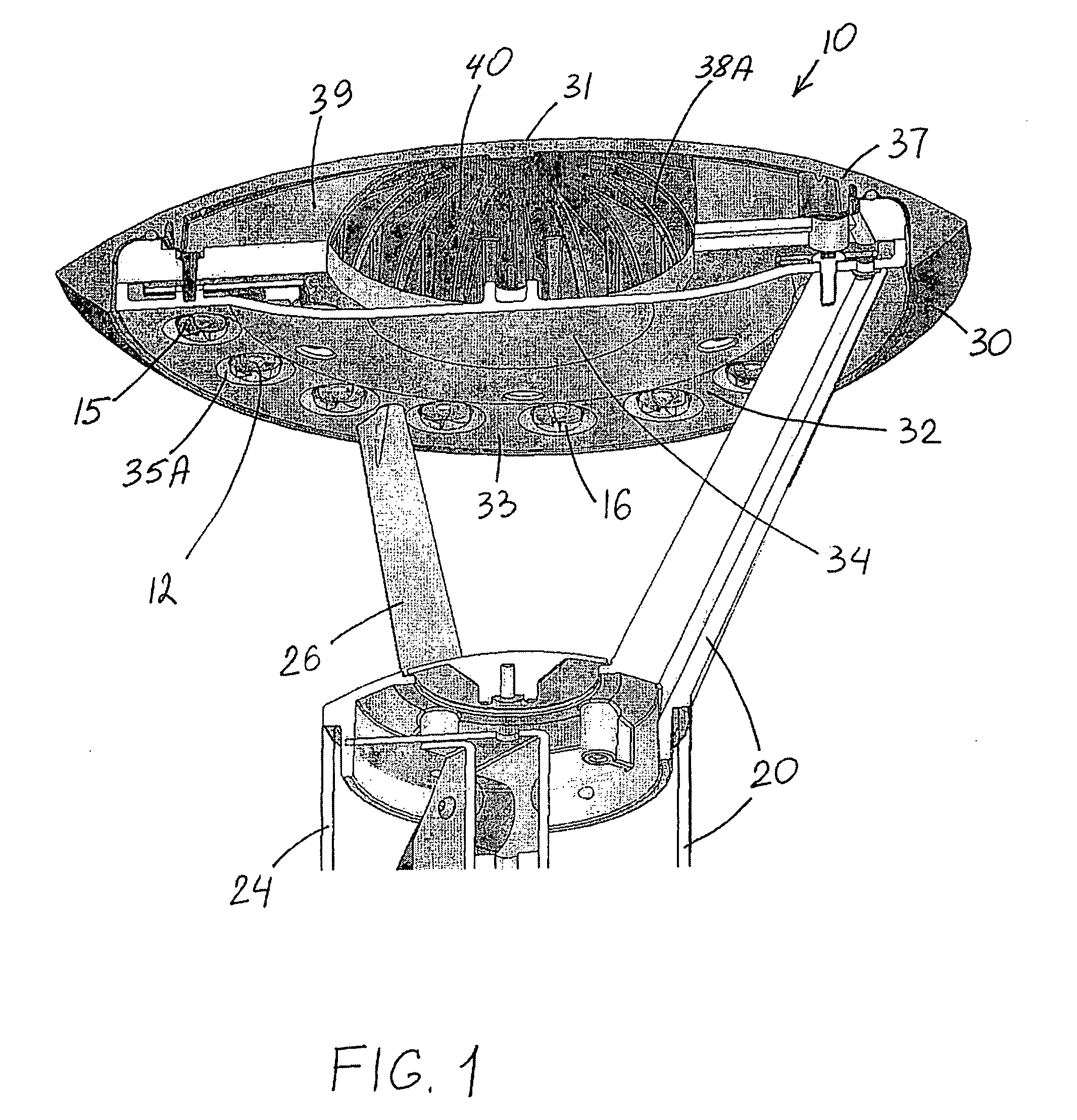
[0042]FIGS. 1-9 illustrate preferred LED lighting fixture 10. The lighting fixture 10 includes a support structure 20 which has a horizontal cross-dimension 22, a top structure 30 attached to support structure 20 and extending outwardly beyond support structure 20. Top structure 30 has a bottom surface 32 with peripheral portion 33 surrounding a non-peripheral portion 34, and a plurality of LED emitters 12 positioned on peripheral portion 33 for emitting light in downward direction substantially outside of horizontal cross-dimension 22 of support structure 20.

[0043]As best seen in FIGS. 1, 2 and 4, LED emitters 12 are arranged in an annular configuration. These FIGS. further show that top structure 30 is circular. FIGS. 2 and 4 show that top structure 30 is concentric with support structure 20.

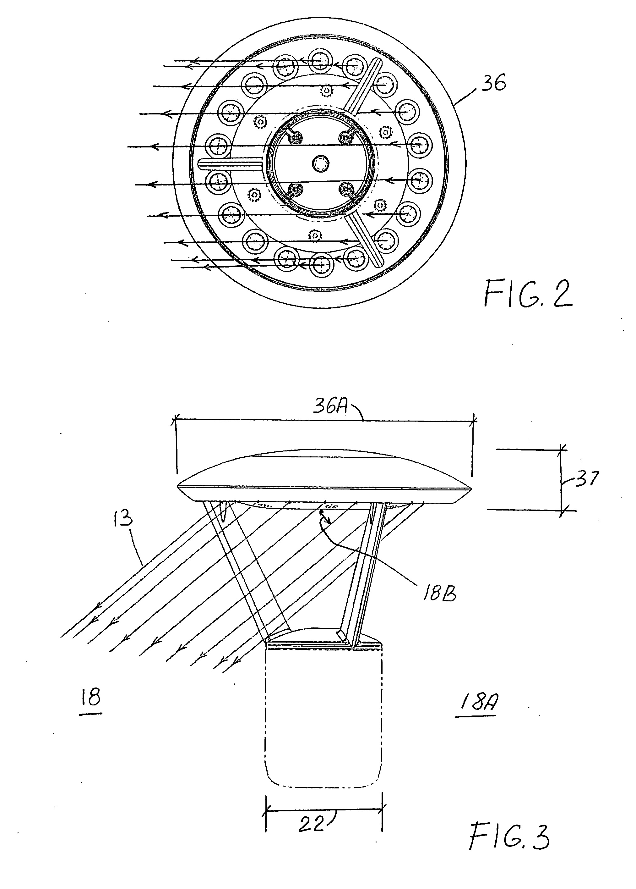
[0044]FIGS. 3, 5, 7 and 9 show that top structure 30 has an outer perimeter 36 which defines a greatest top-structure horizontal dimension 36A. The greatest dimension 37 between bottom surface...


PUM


Abstract

An LED lighting fixture including a support structure having a horizontal cross-dimension; a top structure attached to the support structure and extending outwardly beyond the support structure, the top structure having a bottom surface with peripheral portion surrounding a non-peripheral portion; and a plurality of LED emitters positioned on the peripheral portion for emitting light in downward direction substantially outside of the horizontal cross-dimension of the support structure.

Description

FIELD OF THE INVENTION[0001]This invention relates to light fixtures. More particularly, this invention relates to such light fixtures which utilize LEDs as light source.BACKGROUND OF THE INVENTION[0002]In recent years, the use of light-emitting diodes (LEDs) for various common lighting purposes has increased, and this trend has accelerated as advances have been made in LEDs and in LED-array bearing devices, often referred to as “LED modules.” Indeed, lighting applications which have been served by fixtures using high-intensity discharge (HID) lamps and other light sources are now increasingly beginning to be served by LEDs modules. Such lighting applications include, among a good many others, roadway lighting, parking lot lighting and many other applications. Creative work continues in the field of using LEDs for light fixtures in various applications. It is the latter field to which this invention relates.[0003]High-luminance light fixtures using LEDs as light source for outdoor a...

Claims


Application Information

Patent Timeline
IPC IPC(8): F21S13/14
CPCF21S8/081F21V27/00F21V29/004F21S8/088F21Y2101/02F21Y2103/02F21W2131/103F21Y2103/30F21Y2115/10F21V29/70F21V21/02
Inventor WILCOX, KURT S.
Owner IDEAL IND LIGHTING LLC
Why Eureka
Eureka Blog
Learn More