Anti-collision lighting systems and methods for a micro aerial vehicle

Inactive Publication Date: 2009-12-10
HONEYWELL INT INC
View PDF3 Cites 24 Cited by
  • Summary
  • Abstract
  • Description
  • Claims
  • Application Information

AI Technical Summary

Problems solved by technology

The MAV currently has no dihedrals and, therefore, it is challenging to visually observe and determine which direction

Method used


Image

  • Anti-collision lighting systems and methods for a micro aerial vehicle
  • Anti-collision lighting systems and methods for a micro aerial vehicle
  • Anti-collision lighting systems and methods for a micro aerial vehicle

Examples


Embodiment Construction

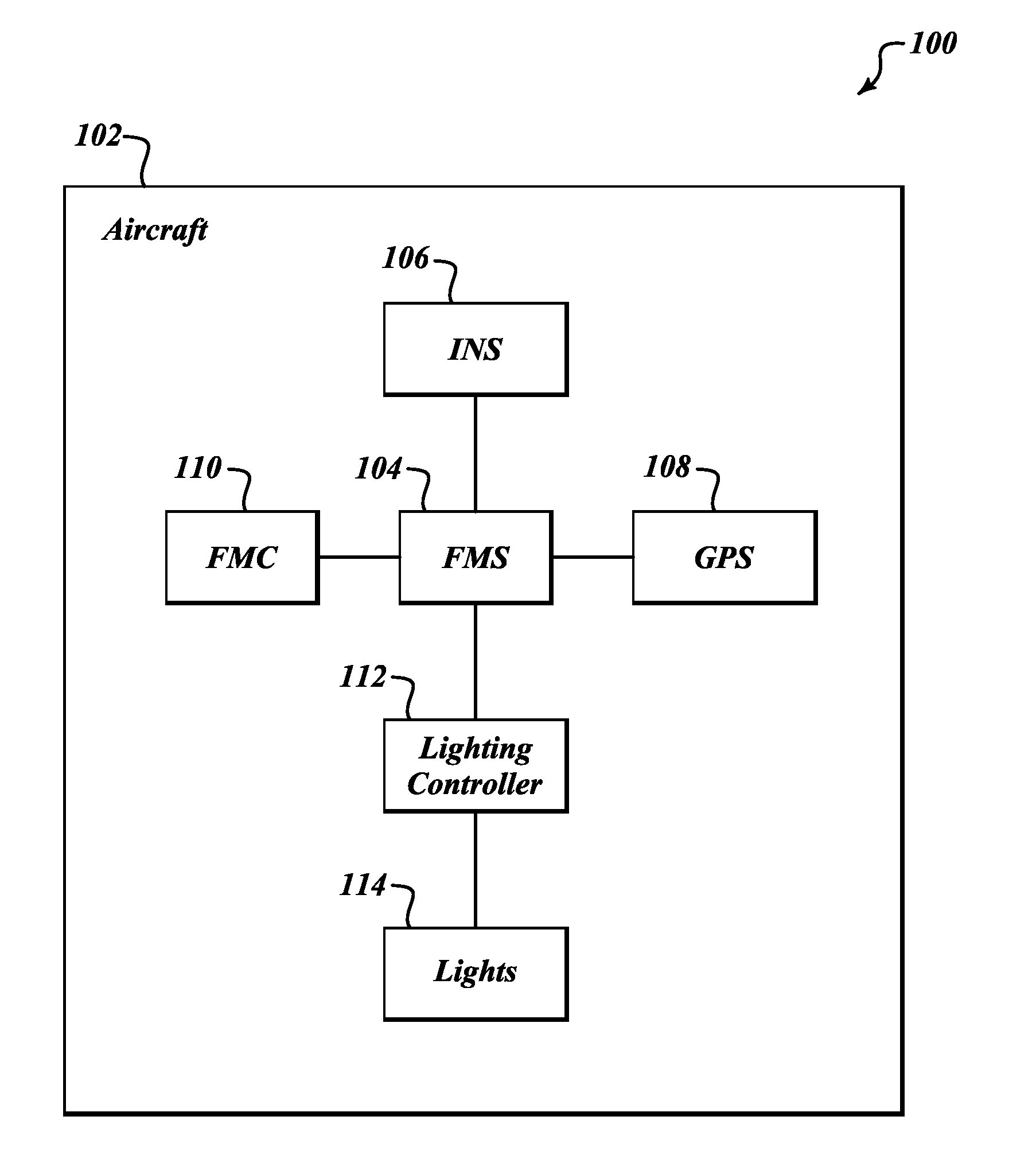
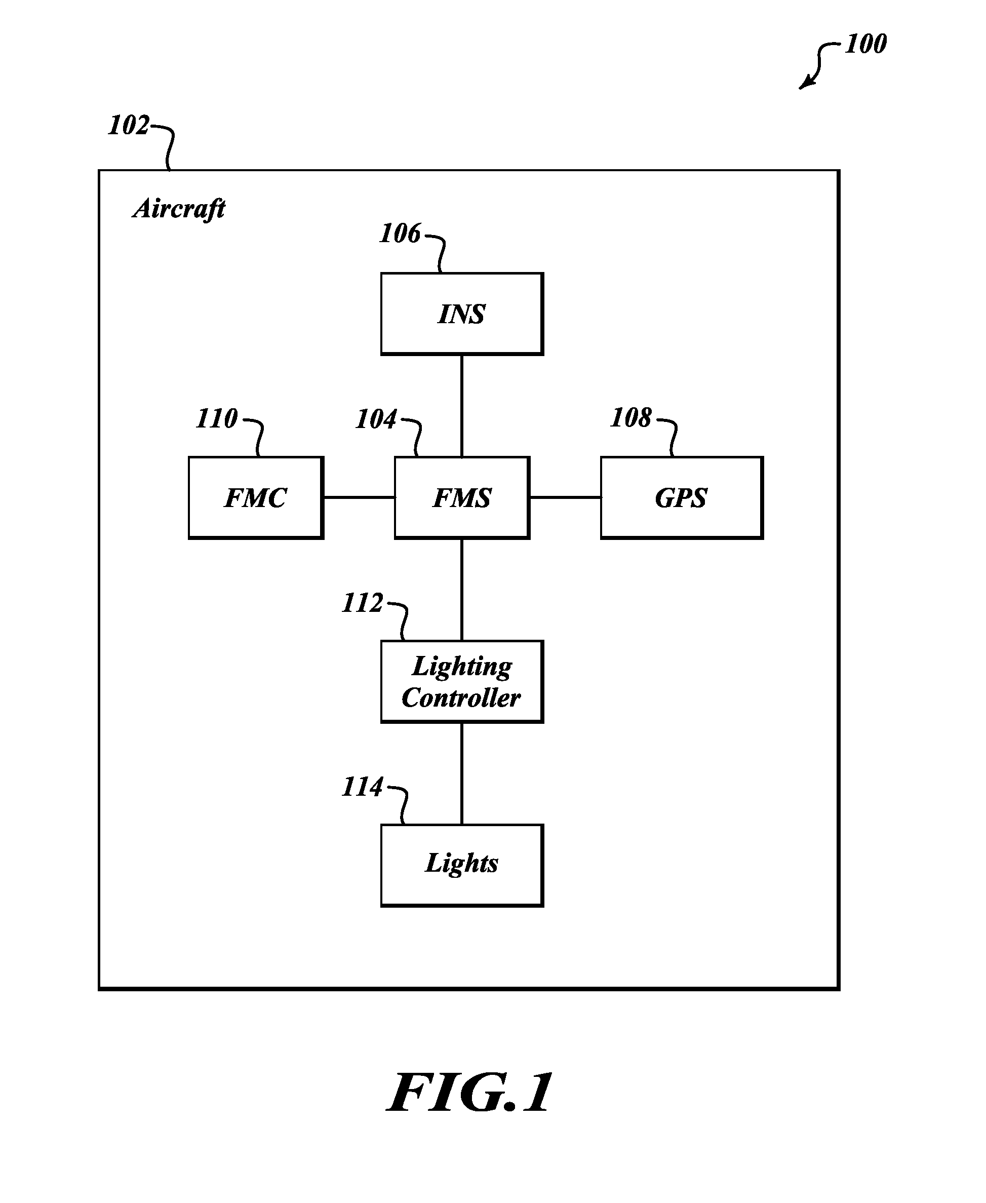
[0013]Systems and methods for anti-collision lights on a UAV are disclosed herein. Currently there are no requirements for navigation / anti-collision lights on a UAV, however, because most UAV's are generally shaped like an airplane, at least during daylight operations the vehicle can be seen by other pilots and can be avoided. MAVs, and in particular ducted fan MAVs are not dihedral in shape, can be cylindrical or circular so there is no clear indication of front and back. In fact the airframe is not limited to moving in one direction. Therefore, as shown in one embodiment of the present invention, lightweight lights are used as a passive anti-collision system. More particularly, lights are used at the corners of the aircraft using similar lighting systems as are required for civilian aircraft. Further, in one embodiment of the present invention lights can be selectively altered depending on the direction of travel, the threat level, and the needs of the MAV. For example, each corne...


PUM


Abstract

Systems and methods for anti-collision lights on a UAV. A method for passive anti-collision lights on a Micro-Aerial Vehicle (“MAV”) including determining a location of the MAV using a flight management computer configured to fly the MAV on a programmed path using data from a global positioning system and an inertial navigation system. The flight management system transmits light activation data and selectively activates at least one navigation light located on a visible surface of the MAV using the light activation data from the flight management computer.

Description

GOVERNMENT INTEREST[0001]The invention described herein was made in the performance of work under U.S. Government Contract No. W56HZV-05-C-0724. The Government may have rights to portions of this invention.BACKGROUND OF THE INVENTION[0002]Aircraft navigation lights are generally located with a red navigation light on the left wingtip leading edge, a green light on the right wingtip leading edge and a white navigation light is as far aft as possible on the tail or each wing tip. High-intensity strobe lights are located on the aircraft to aid in collision avoidance. Navigation lights in civil aviation are required to be operational and to be turned on from sunset to sunrise. High-intensity white strobe lights are part of the anti-collision light system, as well as the aviation red or white rotating beacon. The anti-collision light system (either strobe lights or rotating beacon) is required to be operational and to be turned on for all operating airplanes.[0003]An unmanned, aerial veh...

Claims


Application Information

Patent Timeline
IPC IPC(8): G08B21/00
CPCB64C2201/141B64D47/06B64C2201/145B64U2201/10B64U2201/104
Inventor ANNATI, RICHARD E.EKHAGUERE, DAVID E.
Owner HONEYWELL INT INC
Why Eureka
Try Eureka