
Pivoting flashlight

Inactive Publication Date: 2007-08-09
YU SUN
View PDF13 Cites 8 Cited by
  • Summary
  • Abstract
  • Description
  • Claims
  • Application Information

AI Technical Summary

Benefits of technology

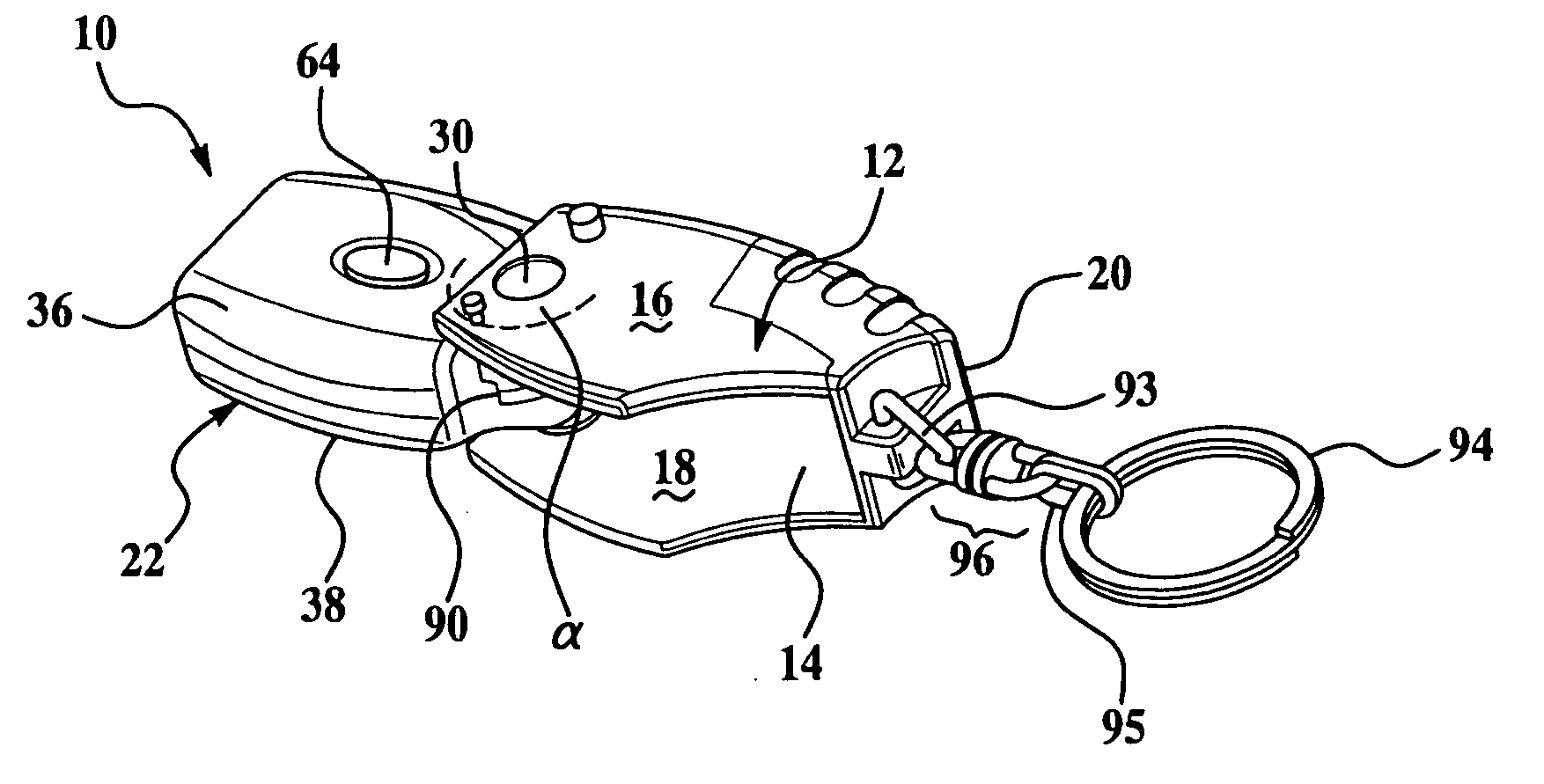
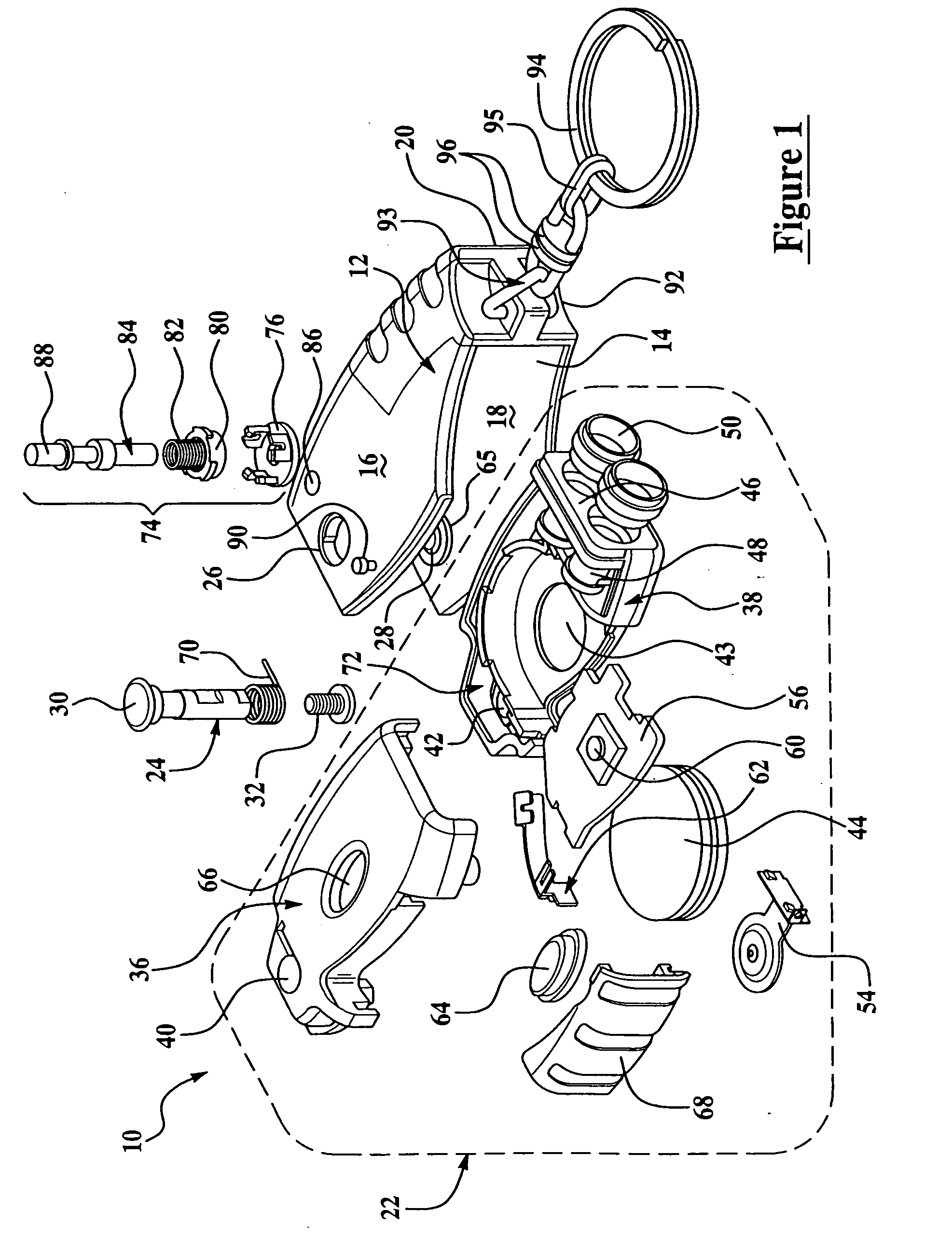
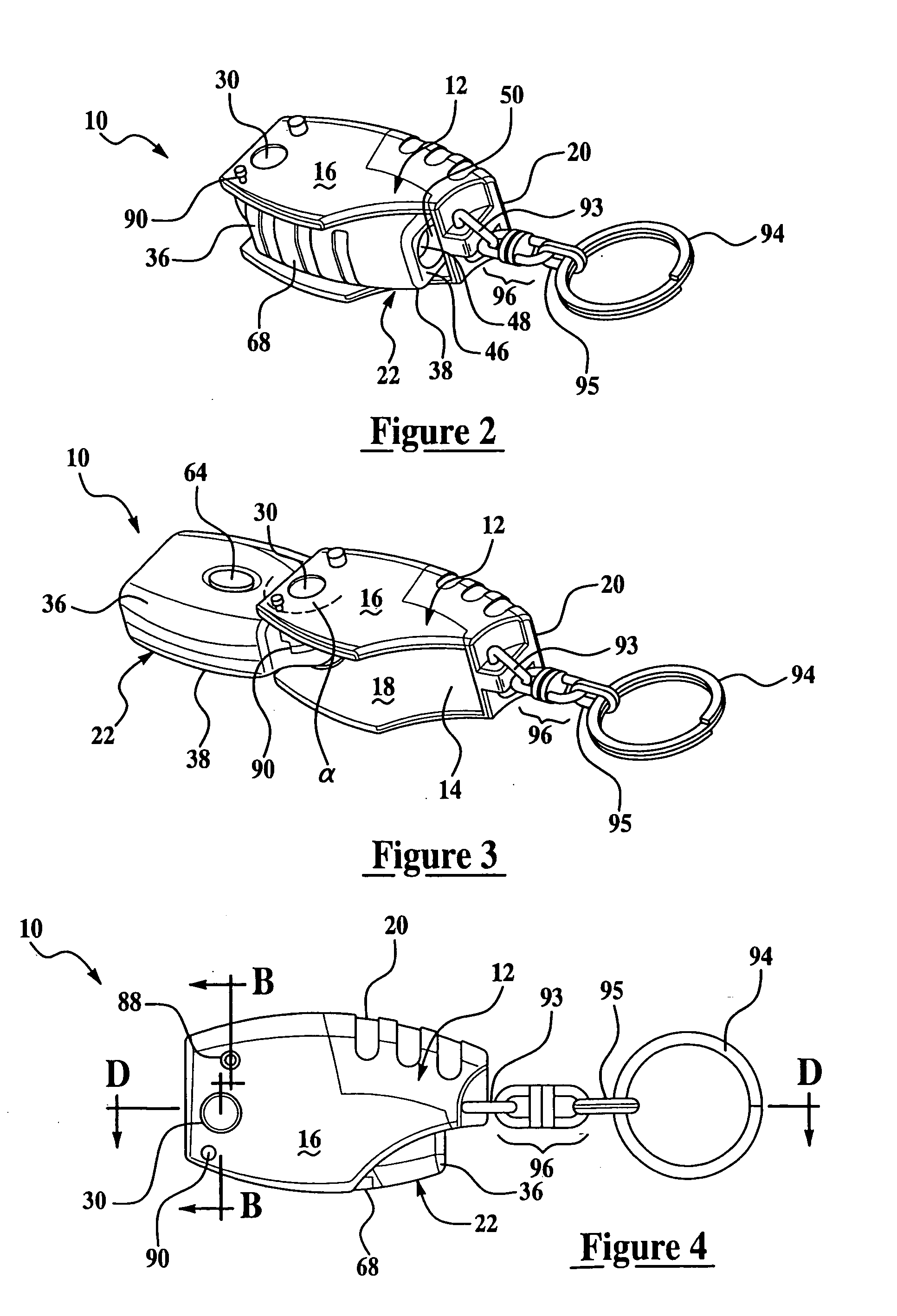
[0004] A flashlight is provided that includes a housing and a light assembly slidable within the housing. The light assembly includes a light source and a battery. A light activation switch is provided for selectively forming an electric circuit between the light source and the battery to induce light emission from the light source. A pivot engages both the housing and the light assembly to rotate the light assembly between a closed position and an extended position relative to the housing. The housing provides a measure of protection to the light activation switch. Optionally, the spring is provided to bias the light assembly towards either of the closed position or the extended position. In combination with an optional spring, a flip switch is optionally added so that upon activation of the flip switch the spring moves the light assembly to an extreme position of open or closed. A keychain ring or other securement is optionally provided to afford ancillary uses for the light. The rotation between extended and closed positions for the light assembly typically ranges between 80 and 200 degrees, and preferably greater than 140 degrees. With the optional addition of a set screw, an intermediate position between closed and open positions is also maintained.

Problems solved by technology

Unfortunately, because of the inadvertent pressure applied to a miniature flashlight within the confines of a pocket, or carrying article such as a purse, the switch for energizing the light is prone to inadvertent depression and concussion damage, with both phenomena limiting the useful lifetime of the flashlight.

Method used


Image

  • Pivoting flashlight
  • Pivoting flashlight
  • Pivoting flashlight

Examples


Embodiment Construction

[0015] The present invention has utility as a miniature flashlight. Through the mounting of a light assembly on a pivot relative to a protective housing, greater longevity is achieved, as compared to a conventional miniature flashlight. It is appreciated that operation of an inventive flashlight is facilitated through the inclusion of a spring to bias the light assembly towards either a fully extended or fully closed position relative to the housing. A flip switch is further optionally provided to release the spring and thereby move the light assembly between closed and extended positions, or vice versa. A light activation switch is readily triggered by the flip switch moving the light assembly into an open position such that upon flip switch activation the light assembly swings into an open position and automatically has a light emission from a light assembly light source.

[0016] Referring now to the figures, an inventive flashlight is depicted generally at 10 where like numerals a...


PUM


Abstract

A flashlight is provided that includes a housing and a light assembly including a light source and a battery. A light activation switch is provided for selectively forming an electric circuit between the light source and the battery to induce light emission from the light source. A pivot engages both the housing and the light assembly to rotate the light assembly between a closed position and an open position relative to the housing. The housing provides a measure of protection to the light activation switch. A spring is provided to bias the light assembly towards either of the closed position or the extended position. In combination with the spring, a flip switch is added so that upon activation of the flip switch the spring moves the light assembly to an extended position. The rotation between extended and closed positions for the light assembly typically ranges between 80 and 200 degrees, and ideally greater than 140 degrees. With the addition of a set screw, an intermediate position between closed and open positions is also maintained.

Description

FIELD OF THE INVENTION [0001] The present invention in general relates to a miniature flashlight and in particular to a miniature flashlight having a spring switch that moves the light between a closed-inactive position and an extended-illuminated position. BACKGROUND OF THE INVENTION [0002] Miniature flashlights in recent years have shifted towards the use of a light emitting diode (LED) as the light source over incandescent bulbs. The net result is that power usage is more efficient and flashlights have become smaller and lighter even while the function remains the same. Miniature flashlights remain well suited for providing proximity lighting to perform tasks such as mating a key with a lock under poor ambient light conditions. Based on typical uses and the desire to remember to carry such a light, miniature lights have typically incorporated a key ring or spring clip. Unfortunately, because of the inadvertent pressure applied to a miniature flashlight within the confines of a po...

Claims


Application Information

Patent Timeline
IPC IPC(8): F21L4/04
CPCF21L4/005F21Y2101/02F21V14/025F21Y2101/00F21Y2115/10
Inventor YU, SUN
Owner YU SUN
Learn More