Non-contact thermometer

a non-contact, thermometer technology, applied in the direction of thermometers using value differences, instruments, optical radiation measurement, etc., can solve the problems of limited use of conventional non-contact thermometers, unintentional movement of devices by users when reading temperatur

Active Publication Date: 2009-12-10
BLACK & DECKER INC
View PDF14 Cites 32 Cited by
  • Summary
  • Abstract
  • Description
  • Claims
  • Application Information

AI Technical Summary

Benefits of technology

[0007]Additional objects, advantages and novel features of the invention are set forth in part in the description which follows, and in part will become apparent to those skilled in the art upon examination of the following or may be learned by practice of the invention. The objects and advantages of the invention may be realized and attained by means of the instrumentalities and combinations particularly pointed out in the appended claims.

Problems solved by technology

Unfortunately, with these conventional non-contact thermometers, a user may unintentionally move the device when reading the temperature.
However, these conventional non-contact thermometers may be limited in that they can only detect positive temperature changes.

Method used


Image

  • Non-contact thermometer
  • Non-contact thermometer
  • Non-contact thermometer

Examples


Embodiment Construction

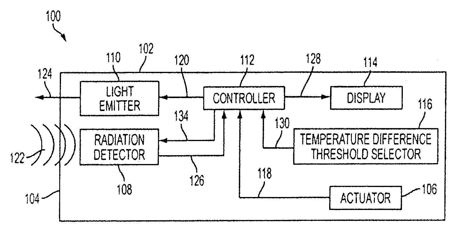
[0019]An exemplary embodiment of a non-contact thermometer in accordance with the present invention will now be described with reference to FIG. 1.

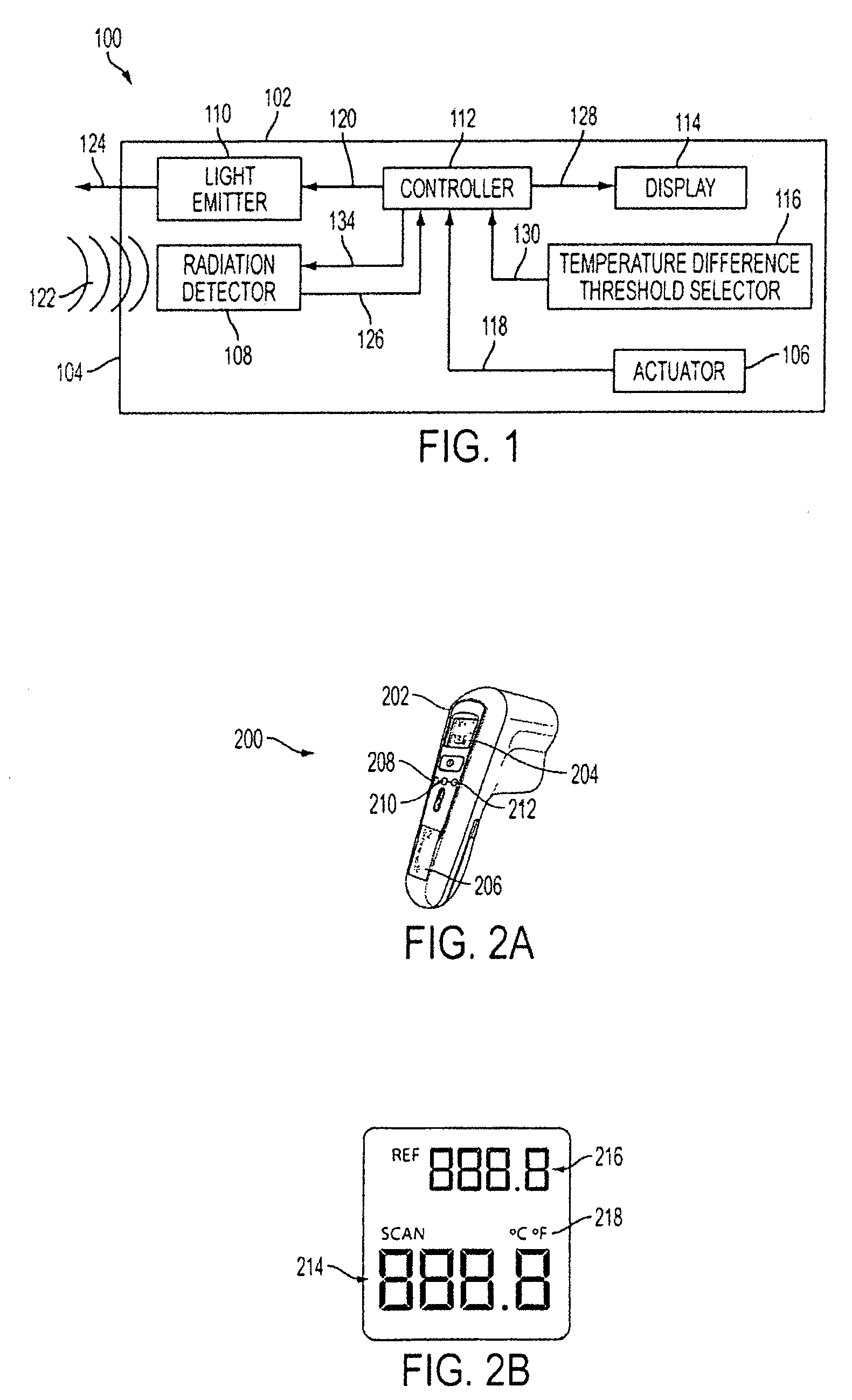
[0020]As illustrated in the figure, non-contact thermometer 100 includes a body 102 having a front face 104, an actuator 106, a radiation detector 108, a light emitter 110, a controller 112, a display 114 and a temperature difference threshold selector 116.

[0021]Actuator 106 may be any device, structure or system that is operable to actuate controller 112 via a signal 118. In an exemplary embodiment, actuator 106 is a button, a trigger, switch or any other device or system apparent to one skilled in the art that may be manipulated by a user. Upon actuation of actuator 106 by a user, signal 118 is generated.

[0022]Radiation detector 108 may be any known device, structure or system that is operable to detect heal-discerning radiation at a remote location, a non-limiting example of which includes an infrared heat detector or thermopile. Once ...


PUM

PropertyMeasurementUnit
temperatureaaaaaaaaaa
temperature differenceaaaaaaaaaa

Abstract

The present invention is drawn to a non-contact thermometer that is operable to emit a first light having a first color to create a spot of a first color at a reference target and to detect the temperature of the reference target. The non-contact thermometer is additionally operable to establish a temperature difference threshold. In use, once a temperature difference threshold is selected and once the temperature of the reference target is detected, the non-contact thermometer may detect a temperature of another target. Further, if the detected temperature of the other target is outside of the temperature difference threshold as compared to the temperature of the reference target, the non-contact thermometer is operable to emit a second light having a second color to create a spot of a second color at the other target.

Description

This application claims the benefit of U.S. Provisional Application No. 61 / 060,099, filed Jun. 9, 2008, the entire disclosure of which is incorporated herein by reference.BACKGROUND[0001]Non-contact thermometers are commonly used for remote temperature detection. Some conventional non-contact thermometers make use of an infrared heat detector known in the art as a thermopile, wherein when the non-contact thermometer device is pointed at a first target and the thermopile detects the temperature at the first target, it displays the temperature on the device. The user must then look at the device to read the measured temperature. Unfortunately, with these conventional non-contact thermometers, a user may unintentionally move the device when reading the temperature. As such, the temperature actually being measured may not correspond to the first target.[0002]Further, some conventional non-contact thermometers allow the user to set a temperature gradient threshold. With these conventiona...

Claims


Application Information

Patent Timeline
Patent Type & Authority Applications(United States)
IPC IPC(8): G01K3/14G01J5/00
CPCG01J5/02G01J5/026G01J5/08G01J5/025G01J5/0896G01J2005/0081G01J5/0003G01J5/089G01J5/48G01J5/07
Inventor AGRONIN, MICHAEL L.
Owner BLACK & DECKER INC
Why Eureka
Try Eureka