Shoe Sole Element

a sole element and shoe technology, applied in the field of shoe sole elements, can solve the problems of inability to control compression, lack of anatomical guidance, instable positions, etc., and achieve the effect of constant exercis

Active Publication Date: 2009-12-17
ZURINVEST
View PDF35 Cites 62 Cited by
  • Summary
  • Abstract
  • Description
  • Claims
  • Application Information

AI Technical Summary

Benefits of technology

[0014]A shoe according to the invention is based on the insight that the weight of a person is distributed between the heel, the external ridges, and the ball of the foot. It is common knowledge that one of the best ways to look after its feet is to walk in wet sand. The shoe according to the invention creates a natural instability, like walking on wet sand, and therefore requires maintaining balance. This provides a good feeling, and the body has to react. The usual approach for sole and shoe design acknowledges the forward movement, and therefore enables a pivoting across a transverse axis of the shoe. The insole supports the longitudinal arch, and acts as anti-shock pad for the feet.
[0016]A further object of the present invention is to provide an alternative shoe sole allowing compensation of misalignments due to the physical structure of the wearer in lateral as well as longitudinal direction. Furthermore said shoe sole shall be provided with means that provide certain guidance for the wearer. Additionally said shoe sole shall encourage the wearer to constant but limited activity in order to balance the current position which provides a constant training effect.
[0019]Such a midsole element or sole element is attachable to any existing shoe. Preferably the midsole element will be glued to the insole of an existing shoe. Alternatively it may also be an integral part of a shoe sole. The use of a compression element and a hard core have the advantage that the user has to balance the position constantly which provides constant exercise.

Problems solved by technology

Said elements provide good shock absorption, but the lack of guidance in terms of anatomical positions such as for example pronation or subpronation.
Furthermore the limitation of the maximum degree of compensation is provided by the properties of the shock absorption elements, which can cause an uncontrollable compression leading to instable positions.
However, it is a drawback that the compensation is not guided and that the degree of the compensation is not very well adjustable.
Additionally the compensation around a lateral axis seems to be based on random and is also not very well guided.

Method used


Image

  • Shoe Sole Element
  • Shoe Sole Element
  • Shoe Sole Element

Examples


Embodiment Construction

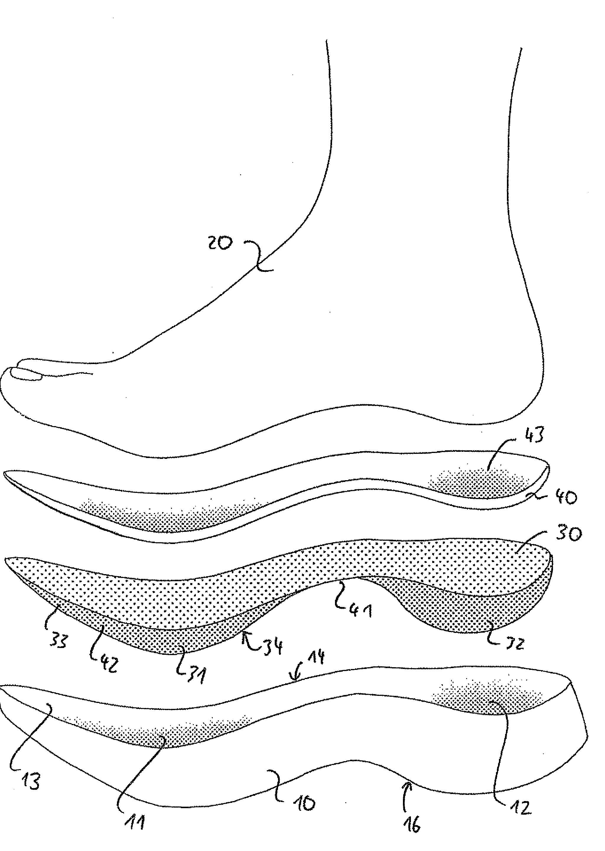
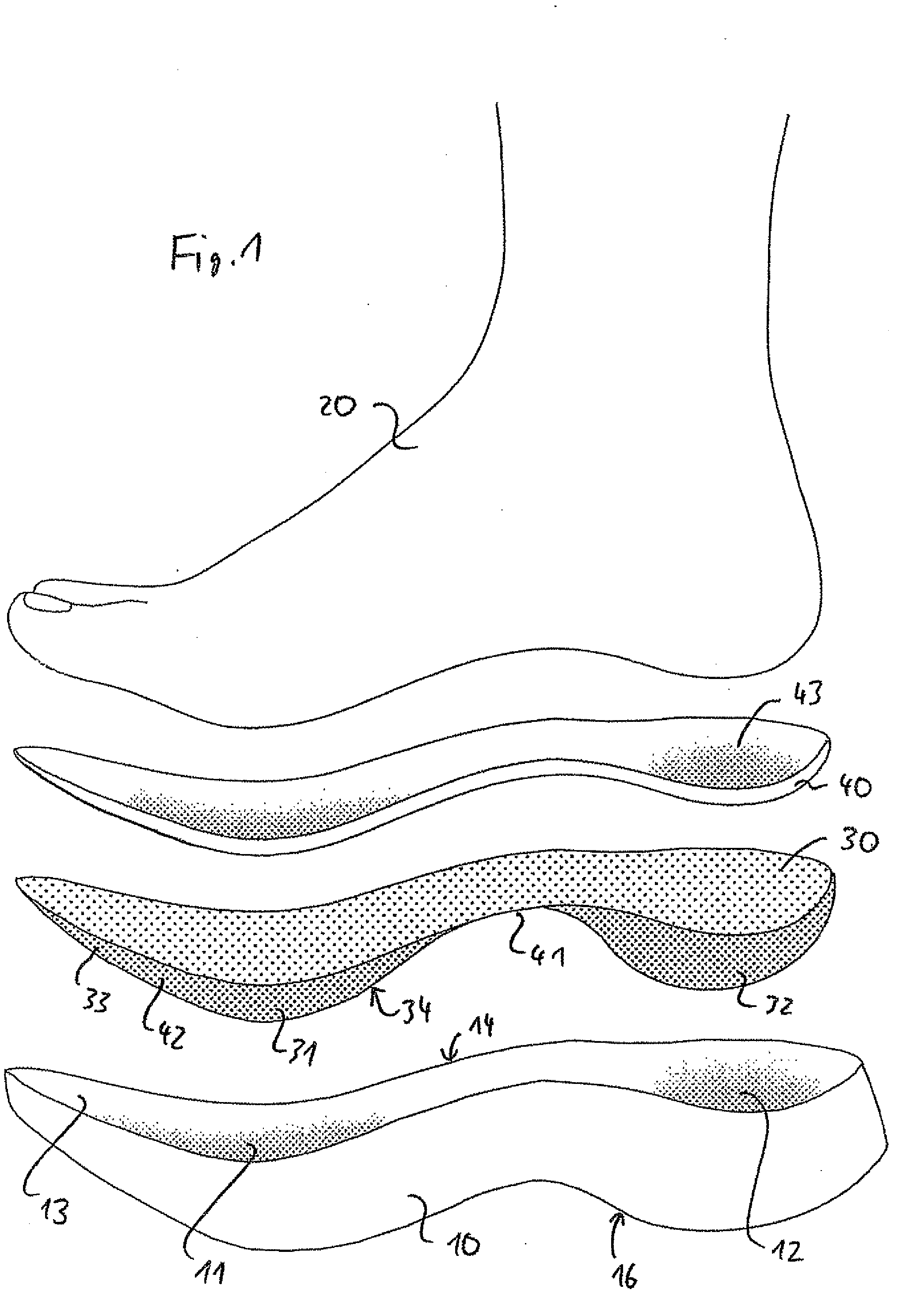
[0060]FIG. 1 shows a schematical representation of an embodiment of the relevant parts of a shoe of the invention, together with the foot of a user to show the different relationships. The upper of the shoe is not shown. The upper can be chosen to suit the application of the shoe. This can be the form of a loafer, a basket shoe, a sneaker, a mid height shoe, a boot, with a shoe heel portion or with a flat lower sole.

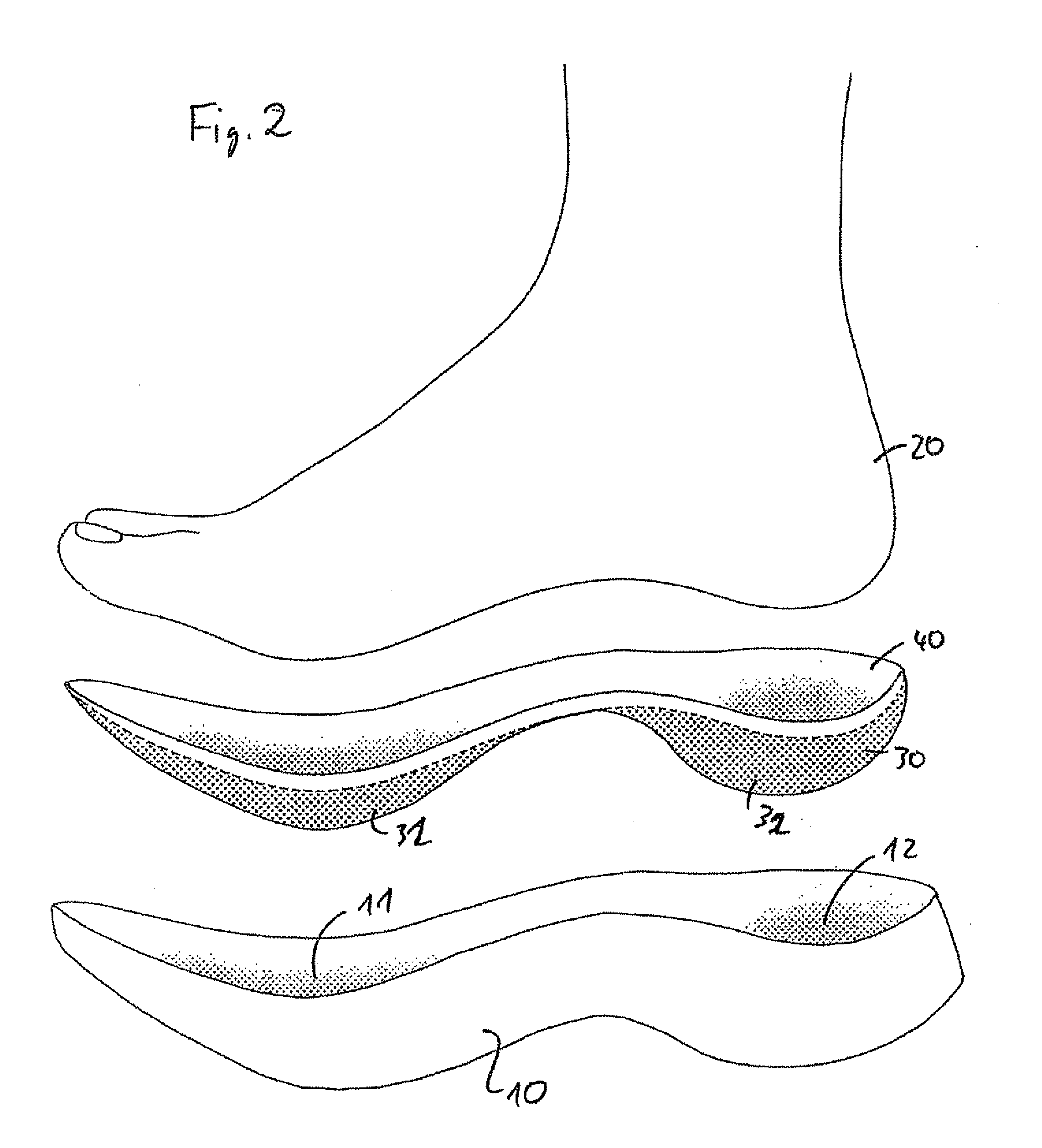
[0061]Reference numeral 10 is provided to show the midsole, and / or outsole unit. The sole 10 can be the outsole, or be part of the outsole. The sole 10 can also comprise the midsole, the layer in between the outsole and the insole, which is typically used for shock absorption. It is relevant for the invention that the sole unit 10 comprises, within the portion which is oriented to the foot 20 of a user, at least two depressions 11 and 12, which can also be qualified as recesses. As it will be explained in connection with FIG. 8, the form of the recess 12 can be a rounded...


PUM


Abstract

A shoe comprises a sole and an insole. The sole comprises an upper surface being in contact with the lower surface of the insole. Said upper surface of the sole comprises at least two depressions being complementary with embossments provided on the lower surface of the insole, allowing a pivoting movement of the front and / or back portion of the insole against the lower outsole surface of the shoe in, at least, an essentially transverse direction to the longitudinal axis of the shoe, when the foot wearing the shoe is pivoted against ground. To support this movement the insole is more rigid than the outsole and is attached to the outsole.

Description

TECHNICAL FIELD OF THE INVENTION [0001]The present invention relates to a shoe sole element having resilient properties.PRIOR ART [0002]Shoe soles having resilient properties are well known from prior art. In particular sport shoes are known to comprise air or gel cushions as shock absorption elements. Said elements provide good shock absorption, but the lack of guidance in terms of anatomical positions such as for example pronation or subpronation. Furthermore the limitation of the maximum degree of compensation is provided by the properties of the shock absorption elements, which can cause an uncontrollable compression leading to instable positions.[0003]Further resilient elements or shock absorption elements are for example known from WO 2003 / 103430. This publication shows a plurality of concepts for providing a shoe sole with resilient properties. With such soles it is possible to compensate lateral anatomic position as named above.[0004]The known soles provide good compensation...

Claims


Application Information

Patent Timeline
Patent Type & Authority Applications(United States)
IPC IPC(8): A43B13/18A43B13/12A43B13/38A43B23/00
CPCA43B7/223A43B13/12A43B13/145A43B13/146A43B21/26A43B13/125
Inventor PFISTER, PATRICK
Owner ZURINVEST
Why Eureka
Try Eureka