Arc containment device and method

a technology of arc containment and containment device, which is applied in the direction of spark plugs, gas-filled discharge tubes, spark gaps details, etc., can solve the problems of pressure or shock wave, insulation breakdown, and the cost of the container increases exponentially with the magnitude of curren

Active Publication Date: 2009-12-17
ABB SPA
View PDF47 Cites 42 Cited by
  • Summary
  • Abstract
  • Description
  • Claims
  • Application Information

AI Technical Summary

Problems solved by technology

This release of energy is in the form of light and heat, often causing a pressure or shock wave.
Arc flashes occur when the insulation between two conductors (often only air) can

Method used


Image

  • Arc containment device and method
  • Arc containment device and method
  • Arc containment device and method

Examples


Embodiment Construction

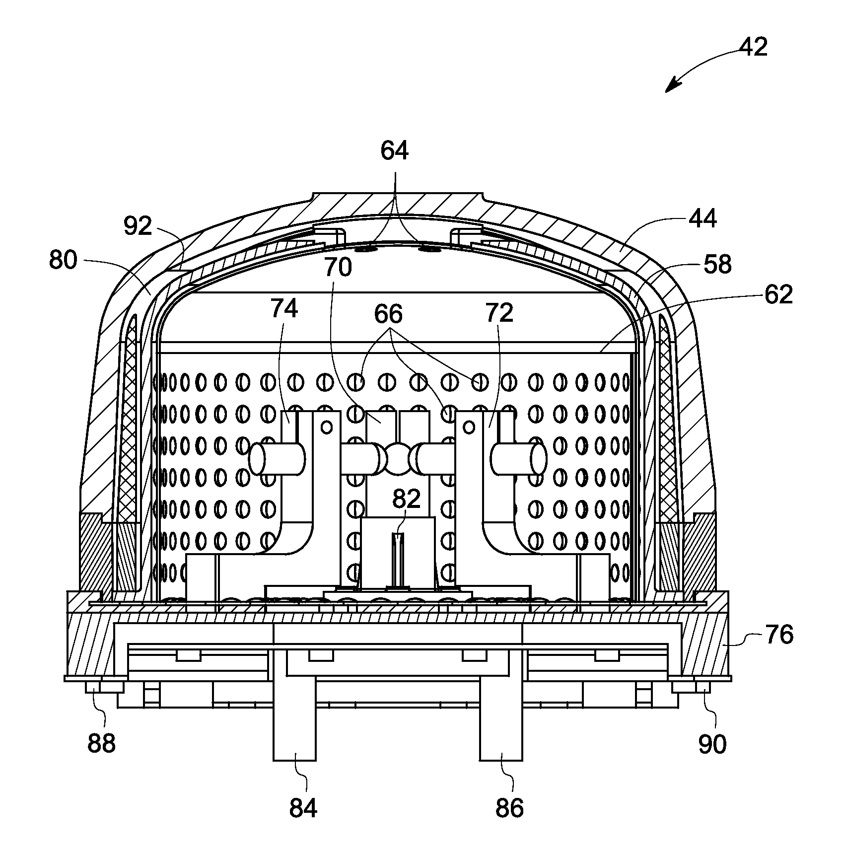
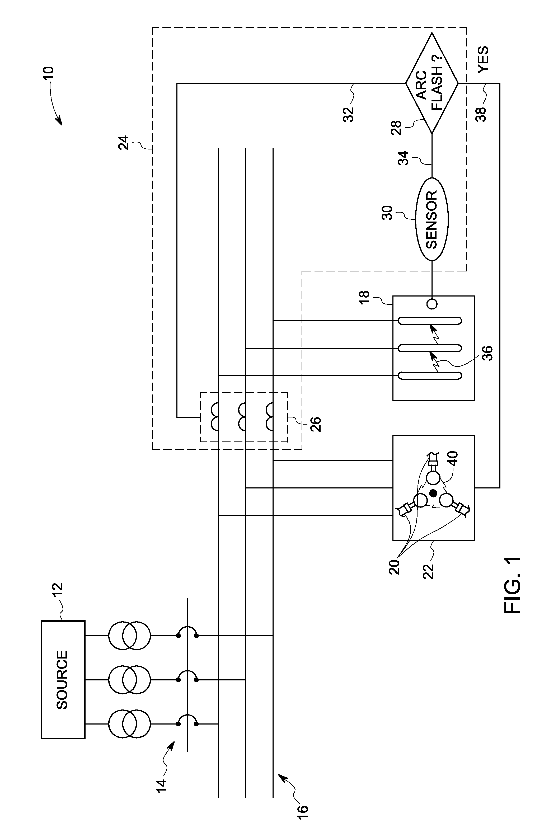
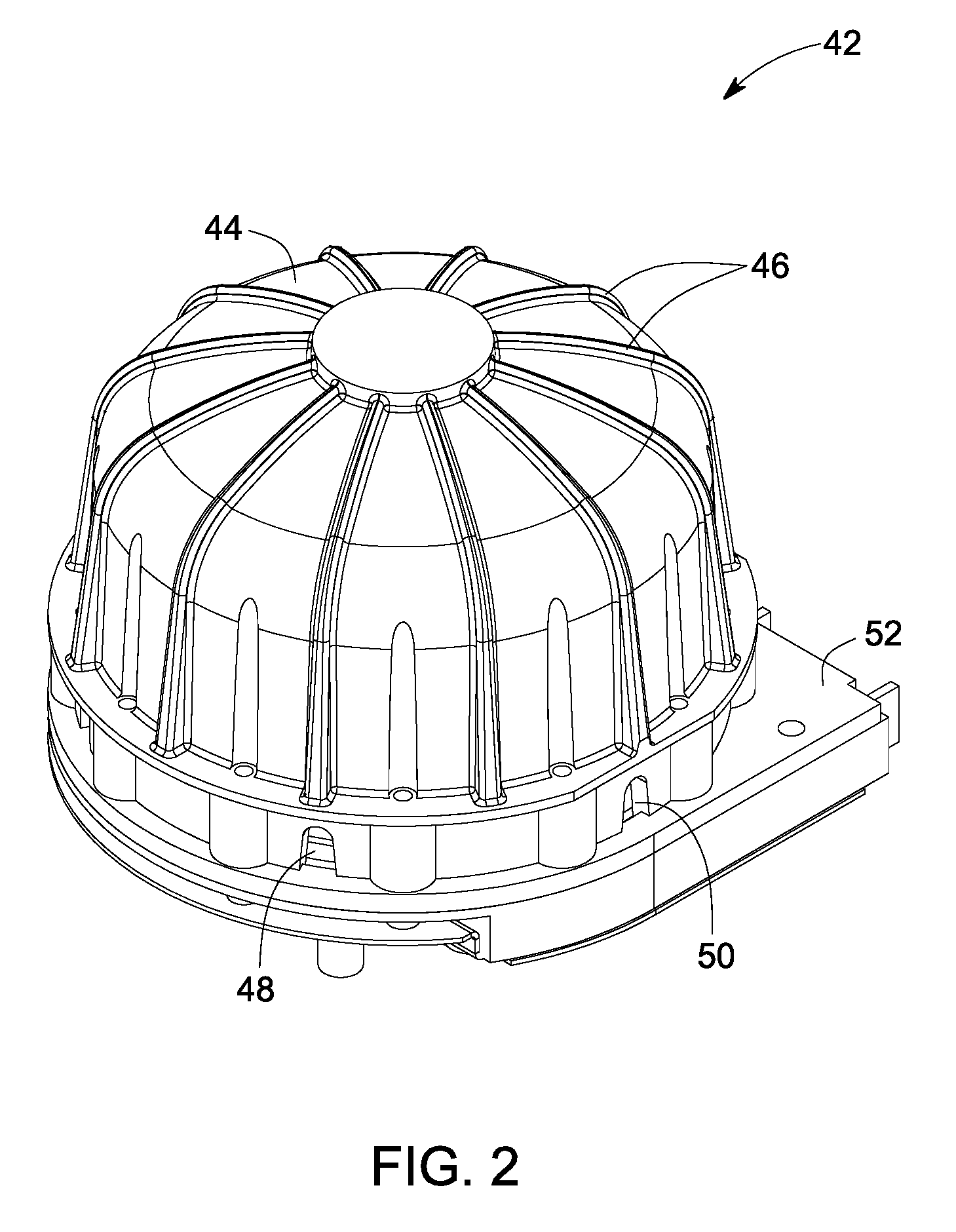
[0016]Referring to FIG. 1, an electrical power system is illustrated and designated generally by the reference numeral 10. In the illustrated embodiment, the electrical power system 10 includes a power source 12 configured to deliver power to a load 18 via a circuit breaker 14. In an exemplary embodiment, the power source 12 is configured to deliver alternating current or AC power to the common bus 16. The electrical power system 10 illustrated herein includes a three phase configuration. In another embodiment, the electrical power system 10 may include a single phase configuration. The power source 12 and the load 18 are further coupled via a common bus 16 to an arc electrode system 20 (arc source). An example of the arc electrode system 20 includes but not limited to an arc crow bar device. The arc electrode system 20 is enclosed within an arc containment device 22.

[0017]An arc flash detection system 24 is configured to detect an arc flash event 36 within the electrical power syst...


PUM


Abstract

An arc containment device is presented. The arc containment device includes a shock shield further having a multiple apertures for escape of gas, the shock shield configured to surround an arc source. The device further comprises an inner enclosure having a multiple openings generally aligned with the multiple apertures, the inner enclosure configured to provide an electrical insulation base for the arc source. An outer enclosure disposed is provided around the inner enclosure, the outer enclosure configured to direct the gas to the environment outside the device.

Description

BACKGROUND[0001]The invention relates generally to techniques for mitigating the effects of arcs, and more particularly to arc containment.[0002]An arc flash may be defined as a condition associated with the release of energy caused by an electric arc. This release of energy is in the form of light and heat, often causing a pressure or shock wave. Arc flashes occur when the insulation between two conductors (often only air) can no longer withstand the voltage between them, resulting in an insulation breakdown. The energy produced by an arc flash event is a function of the voltage between the conductors, current flow during the event, and the duration of the event. To reduce or mitigate the deleterious effects of these events, design engineers have options such as grounding practices and current limiting fuses to reduce system voltage or fault currents. However, under certain conditions reducing arc fault clearing time is another approach to reducing the let-through energy resulting ...

Claims


Application Information

Patent Timeline
IPC IPC(8): H01H33/02
CPCH01T1/00H01T4/04H01T1/15H01T21/00
Inventor BOHORI, ADNAN KUTUBUDDINROBARGE, DEAN ARTHURCAGGIANO, ROBERT JOSEPHASOKAN, THANGAVELUROSCOE, GEORGE WILLIAM
Owner ABB SPA
Why Eureka
Try Eureka