
Method of Determining True Error Vector Magnitude in a Wireless Lan

a wireless lan and error vector technology, applied in the field of determining can solve the problems of affecting the accuracy of the measurement method, and the procedure is thus relatively time-consuming, so as to achieve the effect of faster and cheaper measurement of the true error vector magnitud

Inactive Publication Date: 2009-12-24
ST ERICSSON SA
View PDF9 Cites 53 Cited by
  • Summary
  • Abstract
  • Description
  • Claims
  • Application Information

AI Technical Summary

Benefits of technology

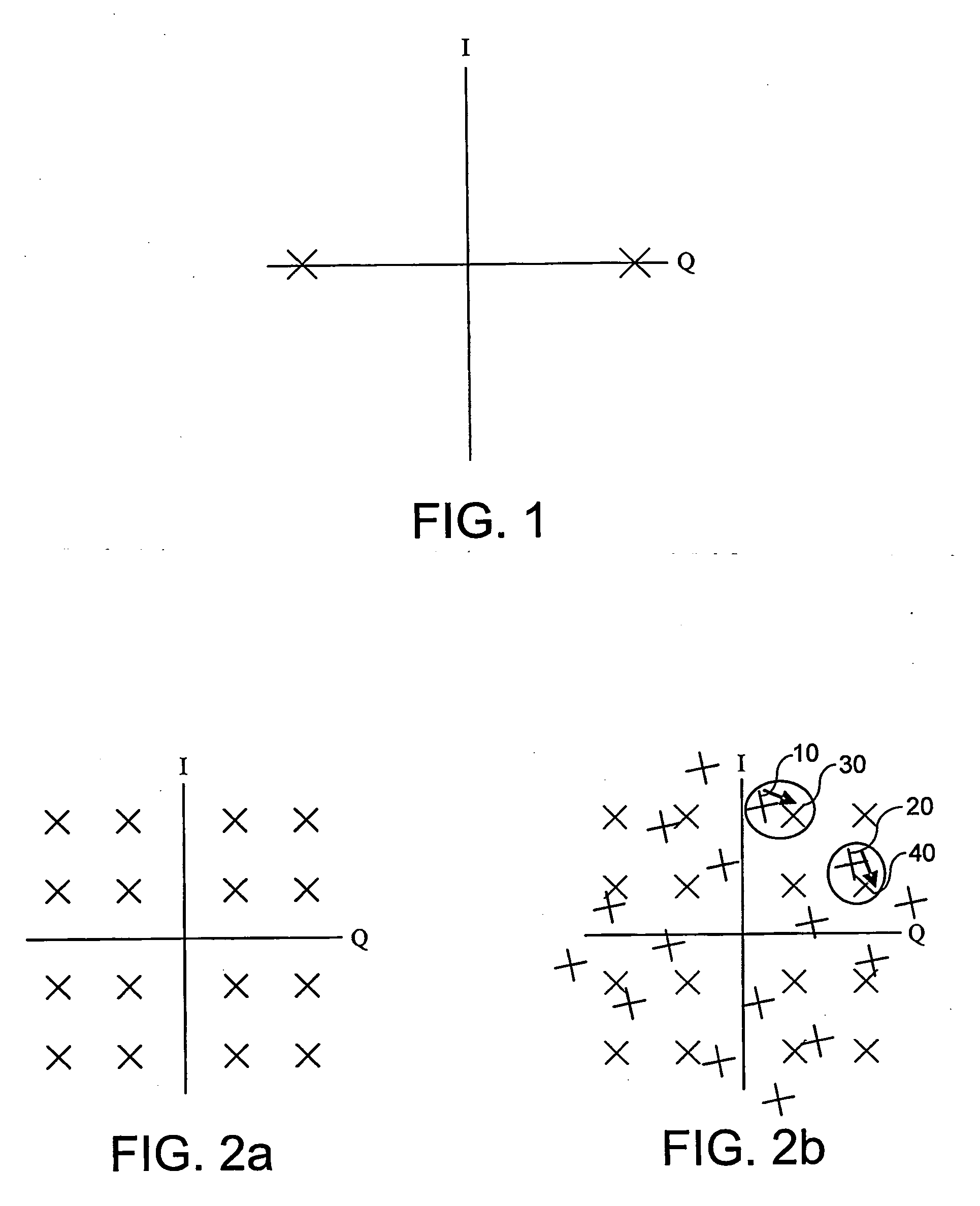
[0017]Using this technique, it is no longer necessary to correct for phase or amplitude imbalances, nor to know in advance what the actual imbalance is. Instead, the actual phase and amplitude is analysed, for example by a statistical analysis, using the fact that each of the measured data points is (or at least should be) clustered around one of a finite and known number of roots in the constellation diagram. This allows the true EVM, resulting only from random phase errors and the like, to be determined without first having to calculate and compensate for the systematic distortions resulting from IQ imbalances. As a result, measurement of the true EVM is faster and cheaper.

Problems solved by technology

However, real transmitters and channels warp the signal being sent, resulting in roots that are shifted from their ideal positions.
These shifts are caused by gain and phase imbalances in the transmit chain, by random phase noise in the transmitter, and by the distortion due to the channel the data is sent over.
In the presence of such shifts, the receiver can incorrectly decode a transmitted root location, because the shifts due to the non-ideal nature of the transmission can result in the roots being moved to (or near) the location of other, equally valid, root locations.
The procedure is thus relatively time-consuming, since it requires two separate tests to be carried out, with a recalculation step in between to take into account the results of the first test.

Method used


Image

  • Method of Determining True Error Vector Magnitude in a Wireless Lan
  • Method of Determining True Error Vector Magnitude in a Wireless Lan
  • Method of Determining True Error Vector Magnitude in a Wireless Lan

Examples


Embodiment Construction

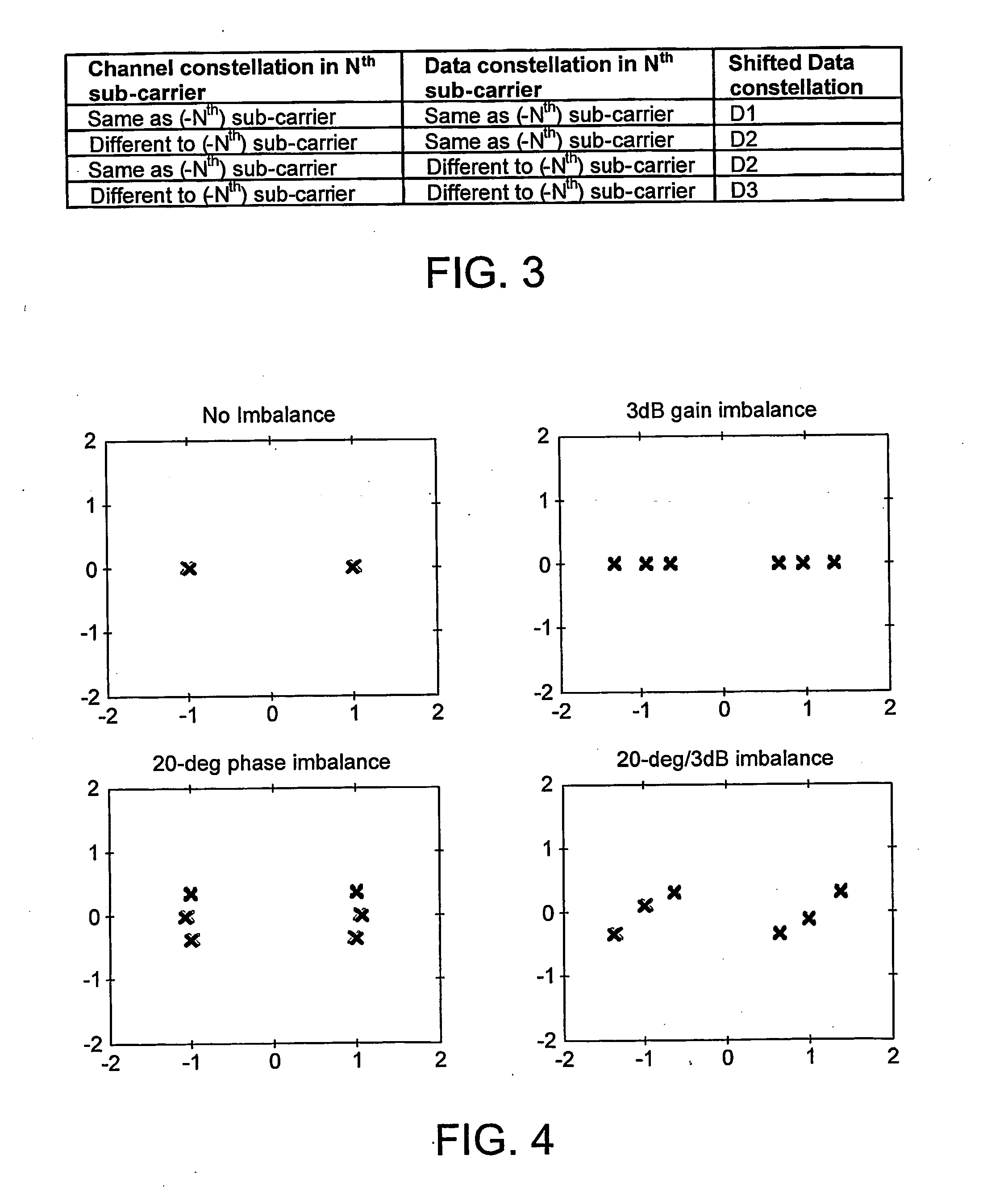
[0025]It can be shown that, in the presence of systematic transmit IQ phase and amplitude imbalances in the transmit chain, the roots of the constellation diagram for a Binary Phase Shift Keyed (BPSK) signal are shifted in the frequency domain to one of the following two possible new positions:

c1=k1(cos(ψ)+sin(ψ))·cc2=k2(cos(ψ)-sin(ψ))·cwherek2=2 / (1+ge);k1=k2·ge;ψ=θ2

where c is the original constellation position (+1 or −1) and ge &θ are the IQ gain phase errors respectively.

[0026]Whether a point in a constellation is shifted to c1 or c2 is dependent on the value of the sub-carrier and its corresponding negative sub-carrier. For example, in BPSK, the constellation point represented by sub-carrier 26 is shifted dependent on the value of the sub-carrier −26. If the values in sub-carrier 26 and −26 are identical, then the constellation points are shifted to location c1. If the values in 26 and −26 are different, the constellation points are instead shifted to c2 in the IQ diagram.

[0027]...


PUM


Abstract

Systematic transmit IQ phase and amplitude imbalances in the transmit chain of a wireless local area network (WLAN) cause a corresponding systematic shift in the roots of a constellation diagram. Additional random phase noise in the transmit chain will cause a further Gaussian distribution of points in the constellation diagram about the systematically shifted roots. This random distribution represents a true error vector magnitude (EVM). By transmitting a known training sequence through the transmit chain, which it is known will be shifted to all of the systematically shifted roots in the constellation diagram, the Gaussian spread around those shifted roots can be analysed to determine the true EVM.

Description

FIELD OF THE INVENTION[0001]The present invention relates to a method of determining a True Error Vector Magnitude (EVM) in a wireless Local Area Network (WLAN).BACKGROUND OF THE INVENTION[0002]Modern high speed wireless Local Area Networks (WLANs) are comprised of a number of individual devices. These can be either clients or access points, and they communicate with each other via wireless links. In order to use these wireless links, each device must have both a transmitter and a receiver. Furthermore, to achieve-optimal performance, the operating characteristics of the transmitting / receiving circuitry must be known. This requires the testing of each transmitter (and receiver) component prior to incorporation into a final WLAN product.[0003]The clients and access points that make up a WLAN communicate with the other clients or access points over the wireless links using one of the many standardized protocols that have been developed for use in WLANs. Some of these protocols, such a...

Claims


Application Information

Patent Timeline
Patent Type & Authority Applications(United States)
IPC IPC(8): H04L12/26G01R29/26H04L1/24H04L27/26H04L27/28H04L27/36
CPCH04L27/364H04L27/2601
Inventor SHAFEEU, HASSAN
Owner ST ERICSSON SA
Learn More