Wide Dynamic Range Microphone

a wide dynamic range, microphone technology, applied in the direction of electrical transducers, gain control, electrostatic transducers of semiconductor, etc., can solve the problem of limiting the application range of the microphone, and achieve the effect of accurate transducing audio signals, low sound pressure, and high top-end

Active Publication Date: 2009-12-24
INVENSENSE
View PDF11 Cites 81 Cited by
  • Summary
  • Abstract
  • Description
  • Claims
  • Application Information

AI Technical Summary

Benefits of technology

[0007]In illustrative embodiments, the microphone system has two transducers. The dynamic range of the first transducer has a relatively low bottom-end so that it can accurately transduce audio signals of relatively low sound pressure. The dynamic range of the second transducer has a relatively high top-end so that it can accurately transduce audio signals of relatively high sound pressure. The dynamic ranges of the two transducers overlap, such that there is a level of sound pressure (or a range of sound pressures) that can be accurately reproduced as an electrical signal by either transducer or both transducers.
[0008]The microphone system may have a selector in some embodiments, so that the system or user can select between transducers depending on the incident sound pressure level. In this way, the microphone system can be made to capture the incident audio signal within the dynamic range of the selected transducer.
[0009]The microphone system also has a summing node or circuit in some embodiments. The summing node or circuit is operably coupled to the plurality of transducers such that the microphone system can provide a signal that is the sum (or weighted sum) of the output of several of the transducers. The microphone system may also have one or more amplifiers in some embodiments to amplify the output of one or more of the transducers so that all transducer outputs are of approximately the same amplitude, which will facilitate the smooth switching among them.

Problems solved by technology

The limited dynamic range of the transducer can limit the scope of applications for the microphone.

Method used


Image

  • Wide Dynamic Range Microphone
  • Wide Dynamic Range Microphone
  • Wide Dynamic Range Microphone

Examples


Embodiment Construction

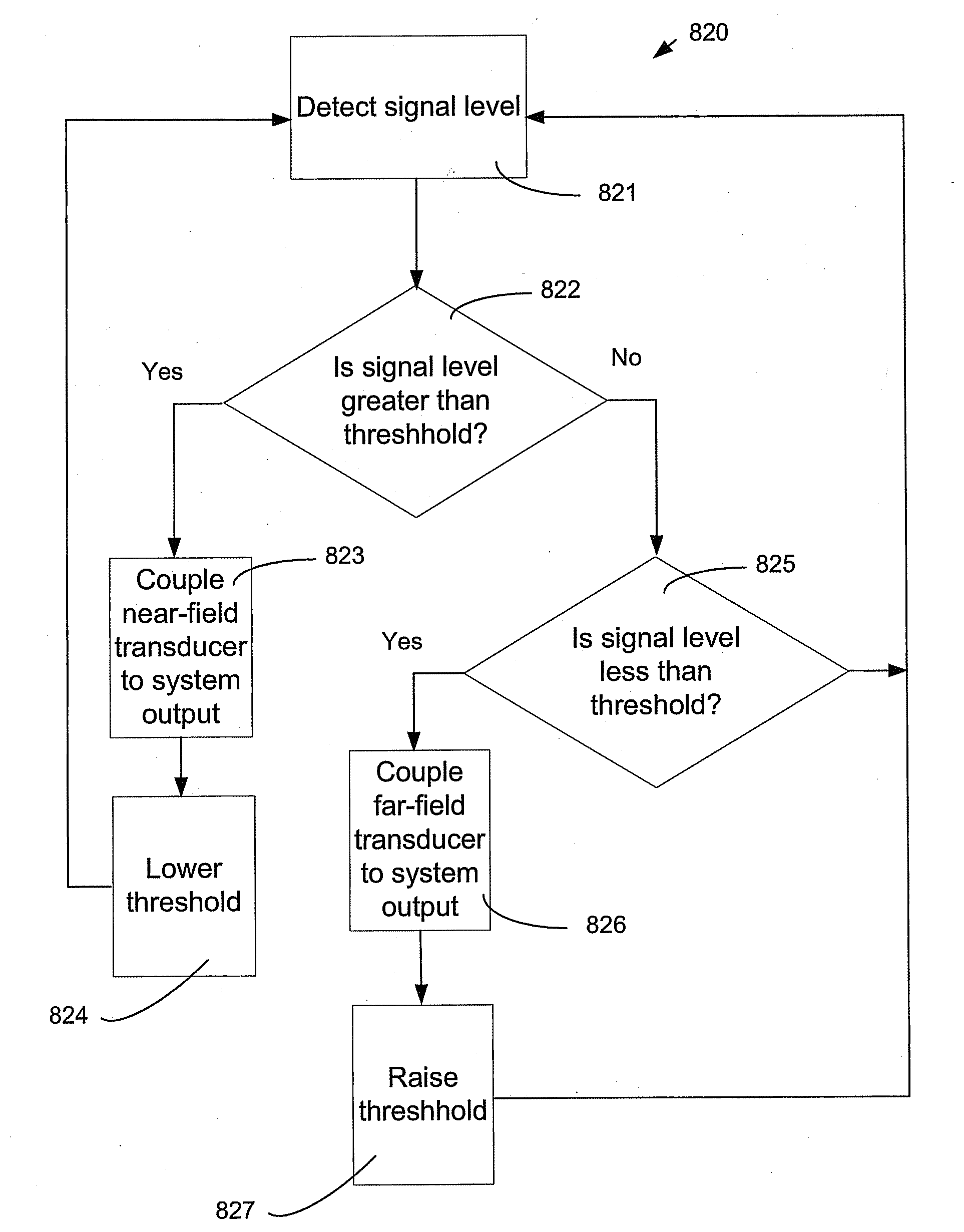
[0032]In illustrative embodiments of the invention, a microphone system has an output and a plurality of transducers, and a selector to selectively couple at least one of the transducers to the output as a function of the amplitude of the incident audio signal, to provide a dynamic range for the microphone system that may exceed that of each individual transducer. To that end, the system may have a plurality of transducers with overlapping dynamic ranges to receive substantially the same incident audio signals. In illustrative embodiments of the invention, a method of operating the system may involve comparing the amplitude of the incident audio signal to a predetermined threshold, and determining which of a plurality of transducers to couple to the system output as a function of whether the amplitude of the incident audio signal is above or below a given threshold. The method may also change the threshold when it has been exceeded. Some methods may create and operate on delayed ver...


PUM


Abstract

A microphone system has an output and at least a first transducer with a first dynamic range, a second transducer with a second dynamic range different than the first dynamic range, and coupling system to selectively couple the output of one of the first transducer or the second transducer to the system output, depending on the magnitude of the input sound signal, to produce a system with a dynamic range greater than the dynamic range of either individual transducer. A method of operating a microphone system includes detecting whether a transducer output crosses a threshold, and if so then selectively coupling another transducer's output to the system output. The threshold may change as a function of which transducer is coupled to the system output. The system and methods may also combine the outputs of more than one transducer in a weighted sum during transition from one transducer output to another, as a function of time or as a function of the amplitude of the incident audio signal. Methods of operating the system may include equalizing the outputs of two or more transducers prior to coupling one or more outputs to the system output.

Description

RELATED APPLICATIONS[0001]This patent application claims priority from provisional U.S. patent application No. 61 / 055,611, filed May 23, 2008, entitled “Wide Dynamic Range Microphone,” the disclosure of which is incorporated herein, in its entirety, by reference.FIELD OF THE INVENTION[0002]The invention generally relates to MEMS microphones and, more particularly, the invention relates to improving the performance of MEMS microphones.BACKGROUND OF THE INVENTION[0003]Condenser MEMS microphones typically have a diaphragm that forms a capacitor with an underlying backplate. Receipt of an audio signal causes the diaphragm to vibrate to form a variable capacitance signal representing the audio signal. This variable capacitance signal can be amplified, recorded, or otherwise transmitted to another electronic device as an electrical signal. Thus the diaphragm and backplate act as a transducer to transform diaphragm vibrations into an electrical signal.[0004]Microphone transducers typically...

Claims


Application Information

Patent Timeline
Patent Type & Authority Applications(United States)
IPC IPC(8): H04R29/00
CPCH04R1/406H04R2499/11H04R19/005H04R3/005H04R17/02H04R2430/00
Inventor HAILA, OLLIHARNEY, KIERANELKO, GARY W.ADAMS, ROBERT
Owner INVENSENSE
Why Eureka
Try Eureka