
Simplifying the creation of user-defined custom elements for use in a graphical modeling application

a graphical modeling and user-defined technology, applied in the field of graphical modeling applications, can solve the problems of static user-defined custom elements created by current mechanisms, inability to be shared among other users without repeating the creation process, and cumbersome mechanisms, so as to achieve the effect of simplifying the creation of user-defined custom elements

Active Publication Date: 2009-12-24
IBM CORP
View PDF14 Cites 95 Cited by
  • Summary
  • Abstract
  • Description
  • Claims
  • Application Information

AI Technical Summary

Benefits of technology

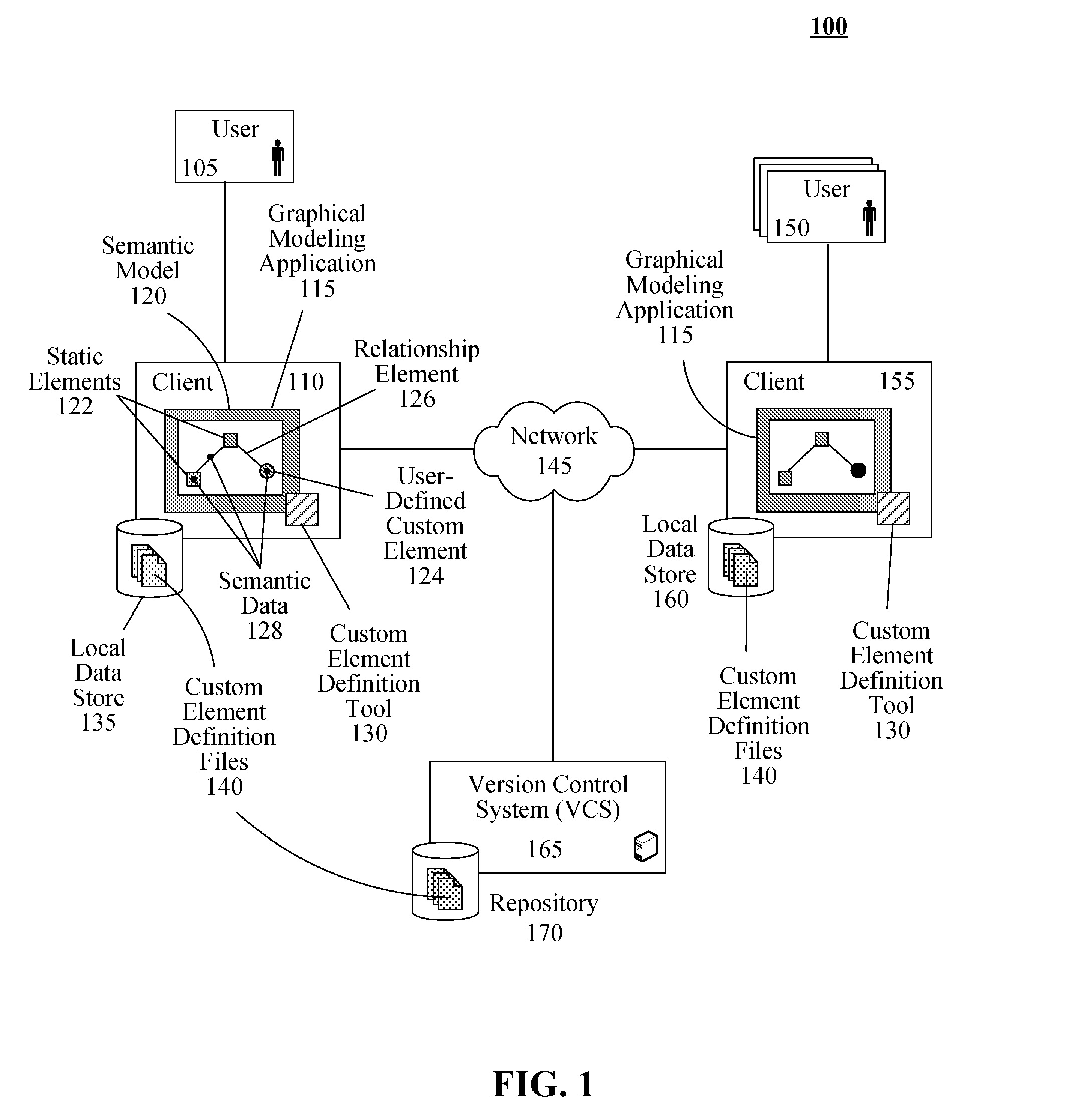
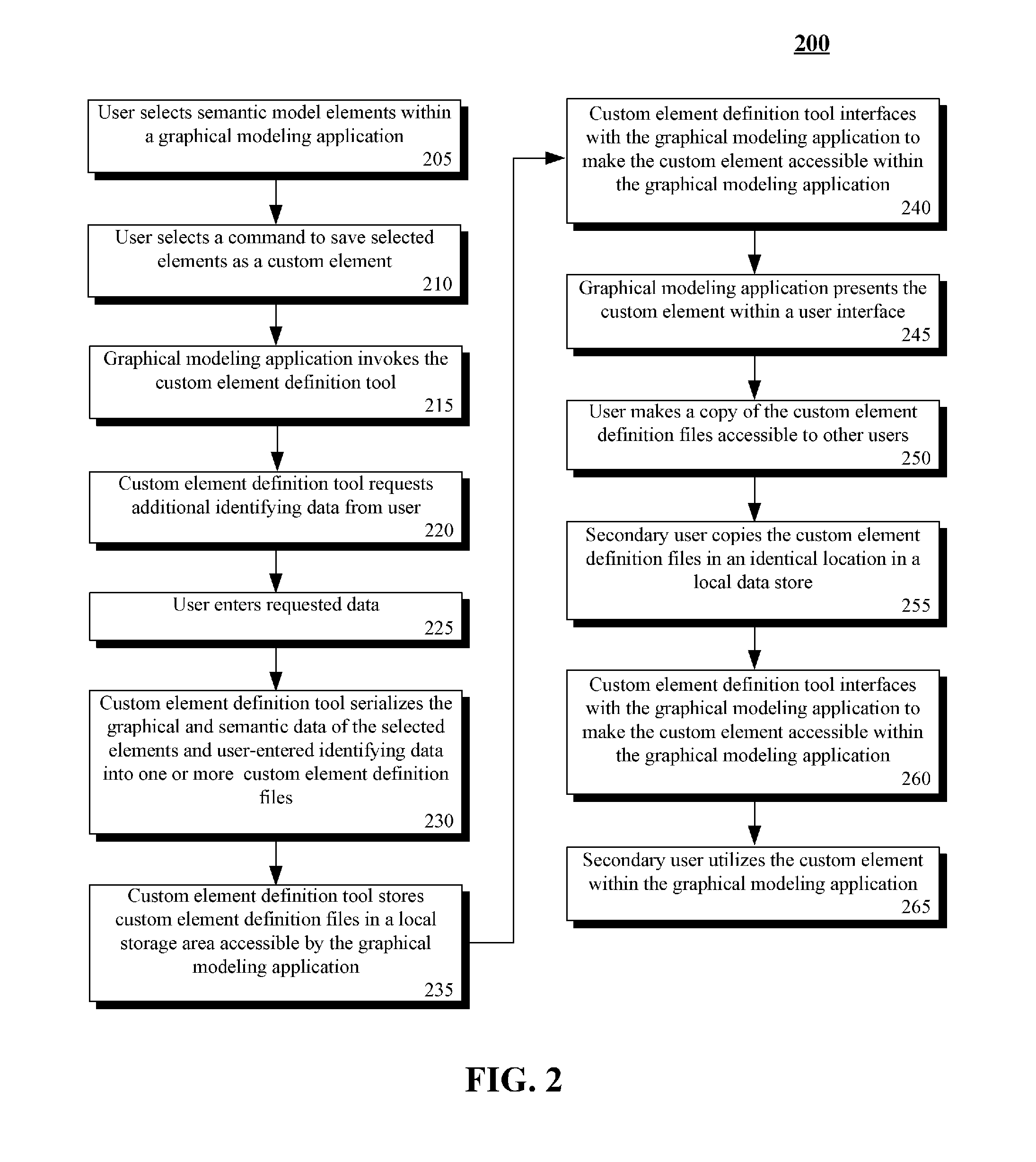
[0006]Another aspect of the present invention can include a method f system that simplifies the creation of user-defined custom elements for use in a graphical modeling application. Compositional and semantic data related to a user-selected static graphical element of a semantic model can be captured within a graphical modeling application. The captured data can be stored as a user-defined custom element within one or more custom element definition files. The custom element definition files can be stored in a user-specified location that is local to and accessible by the graphical modeling application. The user-defined custom element can be automatically registered with the graphical modeling application, making the user-defined custom element accessible within the graphical modeling application.

Problems solved by technology

However, the provided mechanisms are generally cumbersome and require the user to understand how to create the custom element using an application programming interface (API).
Further, the user-defined custom element created by current mechanisms is static and unable to be shared among other users without repeating the creation process.
Current processes, however, still lack simplicity and fail to capture the semantic content of the element.

Method used


Image

  • Simplifying the creation of user-defined custom elements for use in a graphical modeling application
  • Simplifying the creation of user-defined custom elements for use in a graphical modeling application
  • Simplifying the creation of user-defined custom elements for use in a graphical modeling application

Examples


Embodiment Construction

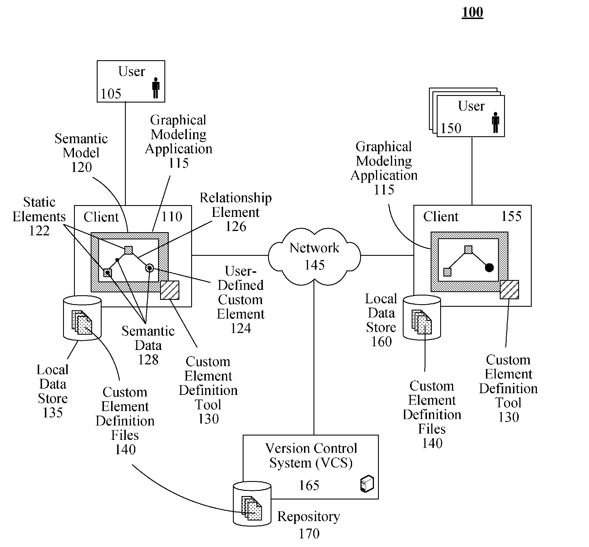
[0012]The present invention discloses a solution that can simplify the creation of user-defined custom elements for use in a graphical modeling application. This solution can utilize a custom element definition tool to capture elements identified by a user within the graphical modeling application. The custom element definition tool can save the captured elements as a user-defined custom element. The user-defined custom element can be stored as one or custom element definition files local to the graphical modeling application. The custom element definition tool can then interface with the graphical modeling application to make the user-define custom element accessible within the graphical modeling application. Further, the custom element definition files can be distributed to other users to share the user-defined custom element.

[0013]The present invention may be embodied as a method, system, or computer program product. Accordingly, the present invention may take the form of an enti...


PUM


Abstract

The present invention can include a solution for capturing user-defined custom elements for use in a graphical modeling application. Such a system can include a graphical modeling application and a custom element definition tool. The graphical modeling application can be configured to create semantic models that contain a static graphical elements and semantic data elements. The custom element definition tool can be configured to create a user-defined custom element for the graphical modeling application. The user-defined custom element can consist of one or more static graphical element and / or one or more semantic data element.

Description

BACKGROUND OF THE INVENTION[0001]The present invention relates to the field of graphical modeling applications, and, more particularly, to simplifying the creation of user-defined custom elements for use in a graphical modeling application.[0002]Graphical modeling applications are popular tools for creating semantic models that are used across a wide variety of disciplines. Generally, a graphical modeling application includes a multitude of static graphical elements, objects and relationships that a user can manipulate when creating a semantic model. Through continued use of the graphical modeling application, users often realize that they are repeatedly creating certain configurations of static graphical elements.[0003]To eliminate this repetitive process, graphical modeling applications often provide a mechanism for the user to save the selected elements as a custom element. However, the provided mechanisms are generally cumbersome and require the user to understand how to create ...

Claims


Application Information

Patent Timeline
Patent Type & Authority Applications(United States)
IPC IPC(8): G06N5/02
CPCG06N5/02
Inventor BERG, DANIEL C.BLANCETT, BRAD L.ELDER, MICHAEL D.HOLLIDAY, CHAD M.MAKIN, NARINDERPOUYER, TIMOTHY A.SNIBLE, EDWARD C.SWANKE, JOHN E.
Owner IBM CORP
Learn More