This helps you quickly interpret patents by identifying the three key elements:
Problems solved by technology
Method used
Benefits of technology
[0018]In an advantageous manner, the lower forward gears and the reverse gears can be activated, via a starting or shift clutch, respectively, hereby to concentrate larger loads to this clutch and, therefore, having the second clutch designed with a more advantageous construction space and lesser cost. In particular, both wheel planes can be positioned in the proposed double clutch transmission, so
Problems solved by technology
Therefore, at least the gear step, in which a range sh
Method used
Image
Click on the blue label to locate the original text in one second.
Reading with bidirectional positioning of images and text.
Examples
first embodiment
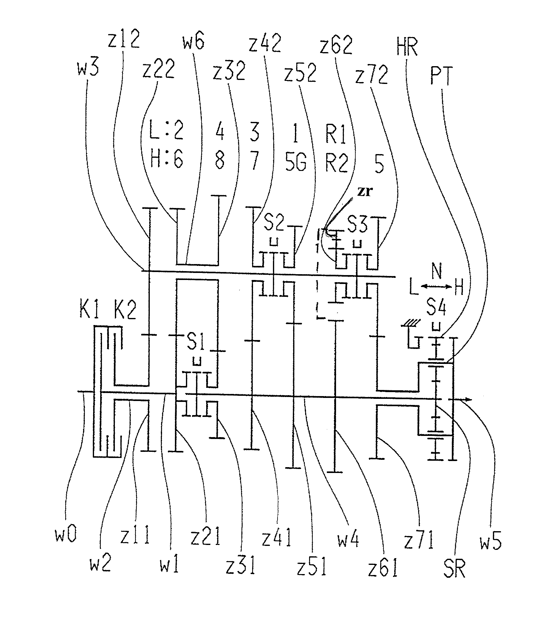
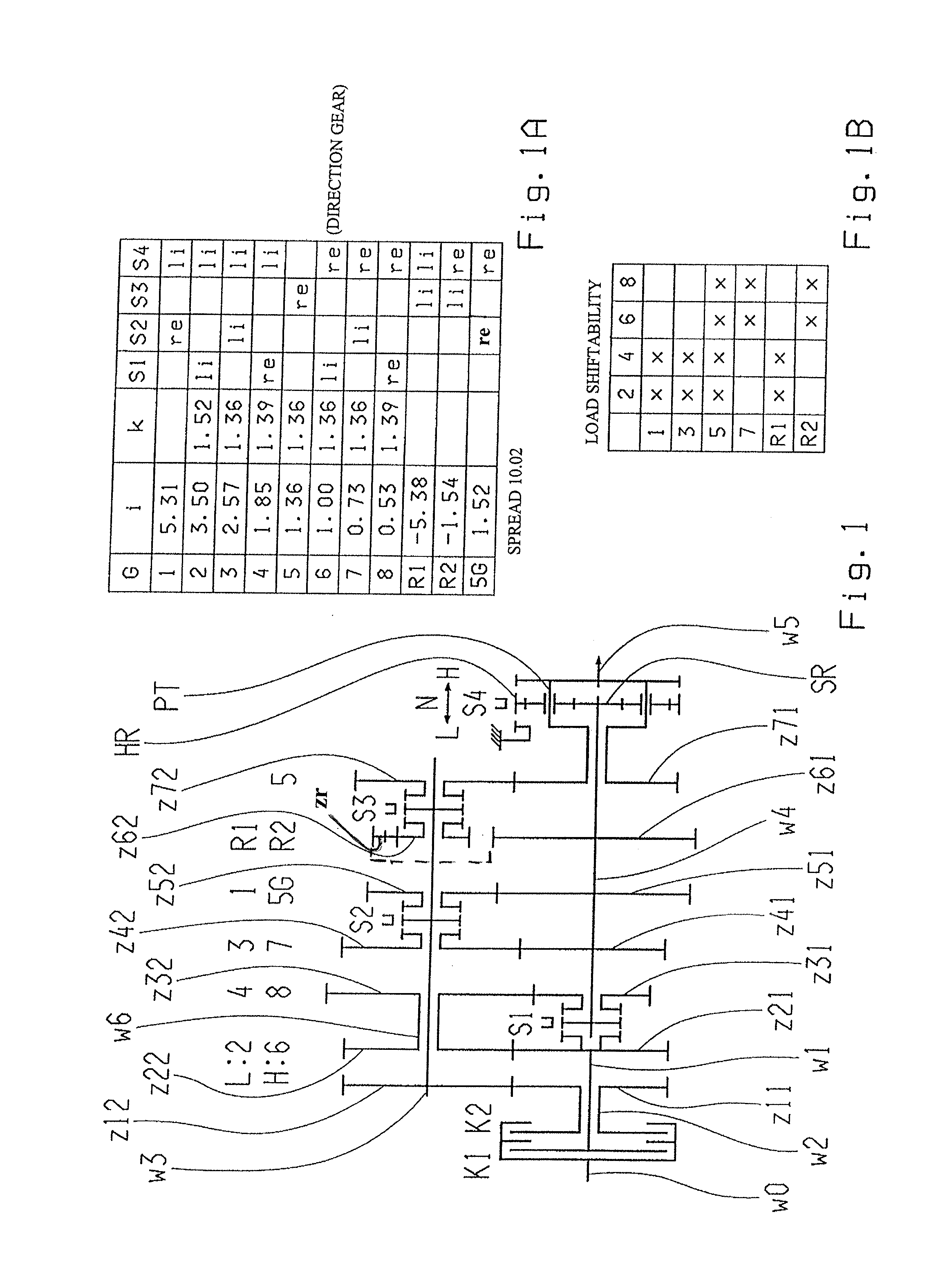
[0035]In a first embodiment variation of the double clutch transmission in accordance with FIGS. 1, 4, and 5, the counter shaft w6, which is connected with the transmission input shaft w1, has two fixed gears z22, z32 assigned thereto. The second counter shaft w3, which is connected with the second transmission input shaft w2, has a fixed gear z12 and four idle gears z42, z52, z62, z72 assigned thereto, whereby the two idle gears z42, z52, by means of the assigned second shift element S2 can be torque proof connected with the second counter shaft w3, depending on the shift direction. The two idle gears z62, z72 are connected by means of the assigned third shift element S3 with the second counter shaft w3, depending on the shift direction. In addition and in this embodiment variation, the main shaft w4 has three fixed gears z41, z51, z61 and two idle gears z31, z71 assigned thereto, whereby the idle gear z31 can be connected with the main shaft w4, via the first assigned shift elemen...
second embodiment
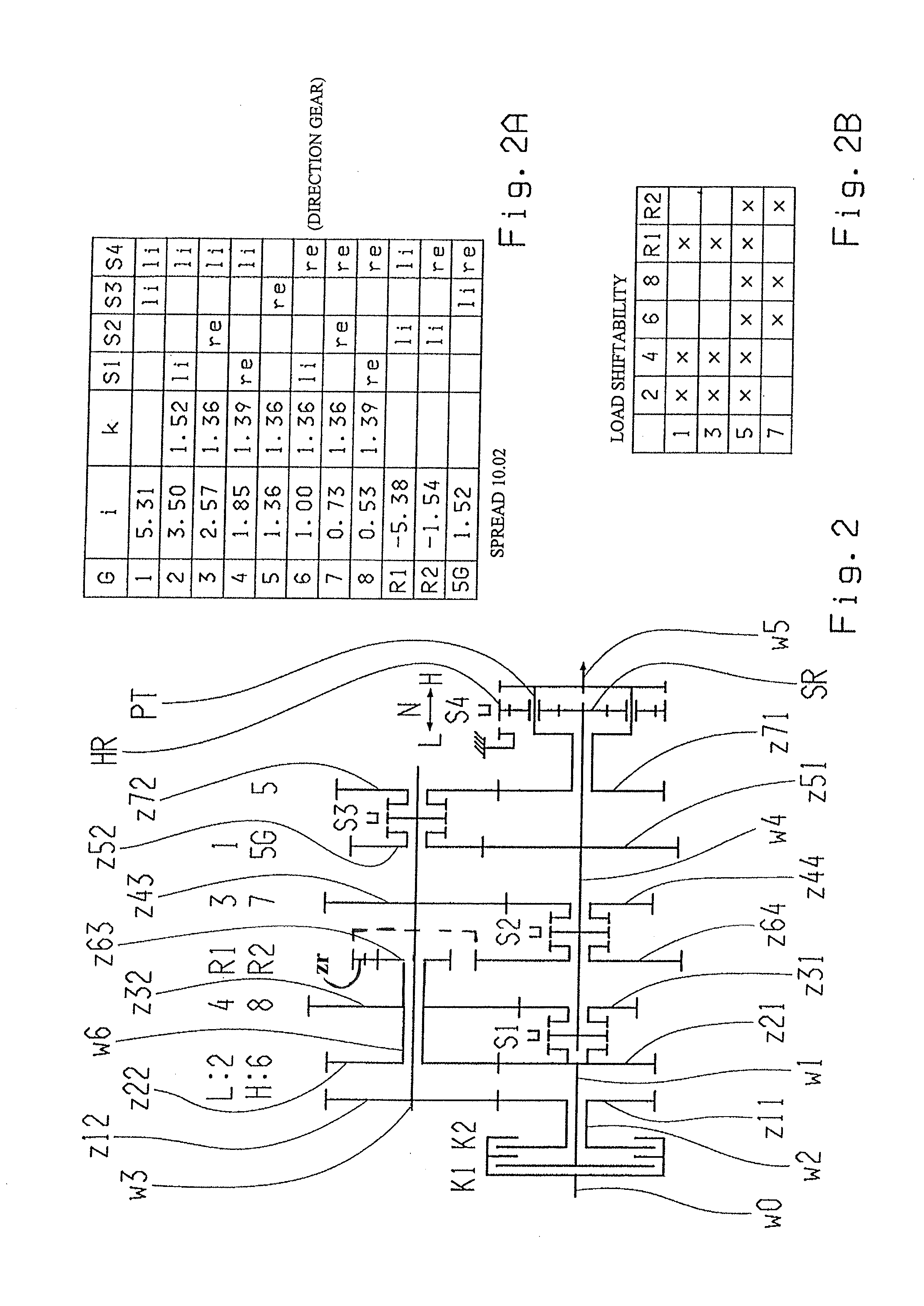
[0046]Thus, in accordance with FIG. 2, this example of the second embodiment variation shows six single-wheel planes and one dual-wheel plane with a total of 15 gear wheels as well as a planetary set, which is designed as a range group.
[0047]The related shift scheme is shown as an example in FIG. 2A with gear ratios l and step increments k, as well as a spread, whereby the actuating direction of the shift elements S1, S2, S3, S4 is marked as li for left and with re four right, in each case in reference to the direction of movement of the schematically shown shift elements in the drawing plane of the drawings.
[0048]As an example in shift scheme, it can be seen that the first forward gear 1 is shifted via the second clutch K2 and via the third shift element S3, which connects via the idle gear z52 with the second counter shaft w3, as well as via the fourth shift element S4, which connects the planetary transmission with the housing via the ring gear HR, whereby the second forward gear...
PUM
Abstract
A double clutch transmission with two clutches (K1, K2) is proposed in which each clutch inputs is connected with a drive shaft (w0) and the clutch outputs are respectively coupled with two, coaxial positioned transmission input shaft (w1, w2) of partial transmissions. The double clutch transmission comprises two counter shafts (w3, w6), coaxial positioned with respect to one another. Each partial transmission has several, shiftable gear ratio steps assigned thereto which each can be coupled with the output shaft (w5), via the assigned counter shaft (w3, w6) and via a main shaft (w4) which is linked to an input section of a planetary transmission which is designed as range group, The output shaft (w5) is positioned coaxially with respect to the driveshaft (w0). At least one shiftable gear ratio step, of at least one of the partial transmissions, can be coupled with the output shaft (w5) independent from the range group.
Description
[0001]This application is a National Stage completion of PCT / EP2012 / 051613 filed Feb. 1, 2012, which claims priority from German patent application serial no. 10 2011 005 028.0 filed Mar. 3, 2011.FIELD OF THE INVENTION[0002]The present invention concerns a double clutch gearbox.BACKGROUND OF THE INVENTION[0003]For instance, a load shiftable group transmission with a double clutch, in which the driveshaft and the output shaft are coaxially positioned to each other, is known through the publication DE 10 2005 044 068 A1. Two transmission input shafts, which are both designed as the partial transmissions, meshing with one another through input constants with one of the counter shafts, whereby the counter shafts are positioned coaxial to one another. Also, the known transmission comprises of a main shaft which can be coupled to shift a direct gear with use one of the transmission input shafts. The output end side of the main shaft is connected with a sun gear which represents the input ...
Claims
Application Information
Patent Timeline
Application Date:The date an application was filed.
Publication Date:The date a patent or application was officially published.
First Publication Date:The earliest publication date of a patent with the same application number.
Issue Date:Publication date of the patent grant document.
PCT Entry Date:The Entry date of PCT National Phase.
Estimated Expiry Date:The statutory expiry date of a patent right according to the Patent Law, and it is the longest term of protection that the patent right can achieve without the termination of the patent right due to other reasons(Term extension factor has been taken into account ).
Invalid Date:Actual expiry date is based on effective date or publication date of legal transaction data of invalid patent.