
Non-pneumatic tire with annular spoke reinforcing web

Inactive Publication Date: 2012-09-20
CATERPILLAR INC
View PDF24 Cites 68 Cited by
  • Summary
  • Abstract
  • Description
  • Claims
  • Application Information

AI Technical Summary

Benefits of technology

[0005]Unfortunately, the provision of such spoke-defining cavities in the side walls of non-pneumatic tires does not completely solve all of the aforementioned problems. Specifically, while the central web of the tire provides good compressive strength in the middle of the tread groove region of the tire at high loads, the applicants have observed that the spokes of such tires may flex in an “S” shaped bending pattern in response to such high loads, the flexing being the most pronounced at the side walls of the tire. The resulting footprint of the tire is rendered non-uniform, with the center portion of the tire tread engaging the ground substantially more than the outer sides of the tire tread, causing higher ground pressure, faster wear, and quicker fatigue failure. Worse still, the rapid flexing and bending of the spokes as the tire rotates generates stress, strain and excessive heat which can degrade the urethane polymer that such tires are typically formed from.
[0006]The invention solves the aforementioned problems with the provision of an annular reinforcing web that interconnects the spokes and increases their bending stiffness, thereby causing the spokes to compress more before bending.
[0007]More specifically, the non-pneumatic tire of the invention includes an inner hoop member having an inner surface that defines the inner diameter of the tire, an outer hoop member having a tread groove region that defines the outer diameter of the tire, and a central web that connects the inner and outer hoop members. A plurality of elongated, radially aligned cavities on either side of the central web defines integrally-formed spokes which connect the inner and outer hoop members. The annular reinforcing web is located on and affixed to either side of a disc-shaped central portion of the central web and interconnects each spoke to the spokes on either side of it thereby rigidifying the spokes. The resulting extra rigidity advantageously causes each spoke to compress more in response to a load before bending, thereby increasing the maximum load that the tire can bear and decreasing the amount of bending of the spokes.
[0008]The annular web is preferably connected to the spokes at a point between about 55% and 80% of their radial extent as measured in the direction from said inner to the outer hoop member, and is more preferably connected to the spokes at a point between about 60% and 75% of their radial extent. Such a connection point provides bending strength in the spokes where it is needed most, which is near the outer hoop member where the spokes are most apt to flex in response to a high compressive load.

Problems solved by technology

Unfortunately, the provision of such spoke-defining cavities in the side walls of non-pneumatic tires does not completely solve all of the aforementioned problems.
The resulting footprint of the tire is rendered non-uniform, with the center portion of the tire tread engaging the ground substantially more than the outer sides of the tire tread, causing higher ground pressure, faster wear, and quicker fatigue failure.
Worse still, the rapid flexing and bending of the spokes as the tire rotates generates stress, strain and excessive heat which can degrade the urethane polymer that such tires are typically formed from.

Method used


Image

  • Non-pneumatic tire with annular spoke reinforcing web
  • Non-pneumatic tire with annular spoke reinforcing web
  • Non-pneumatic tire with annular spoke reinforcing web

Examples


Embodiment Construction

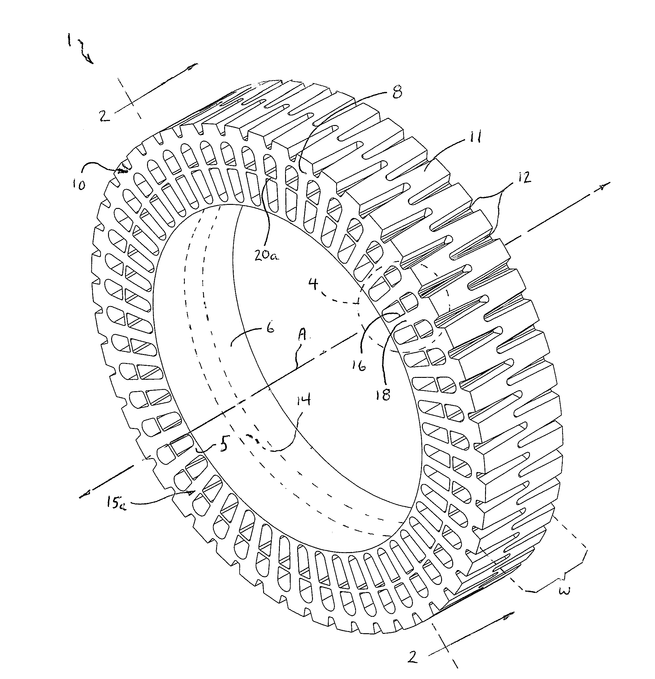
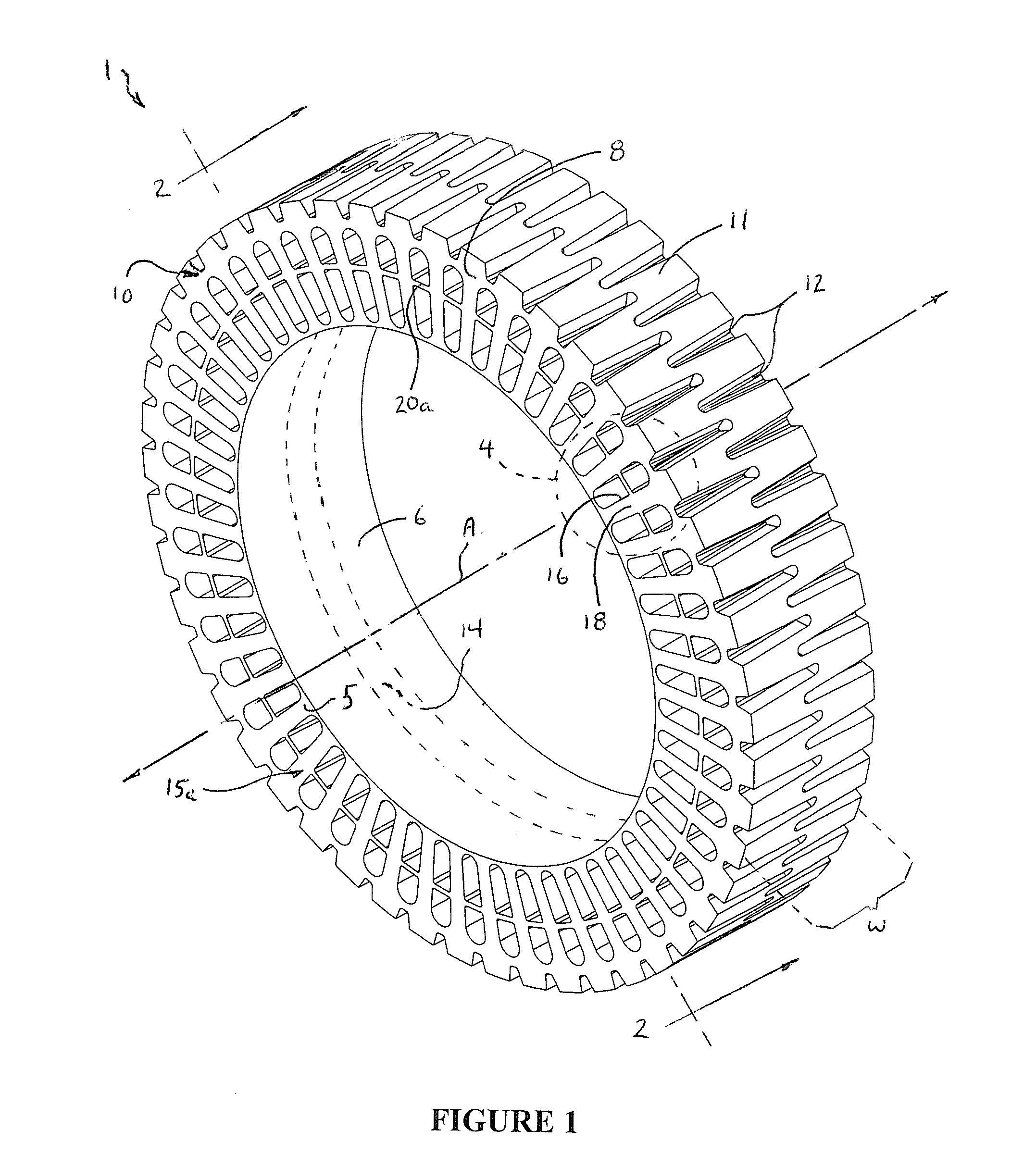
[0017]With reference now to FIGS. 1 and 2, wherein like numbers designate like components throughout all of the several Figures, the non-pneumatic tire 1 of the invention generally comprises an inner hoop member 5 having an inner surface 6, and an outer hoop member 8 having a tread groove region 10. Tread groove region 10 includes an outer surface 11 with treads 12 which in this example are parallel to the axis A of rotation of the tire 1. The treads 12 extend a little over half the width of the tire 1, and are staggered with respect to each other. Of course, any one of a number of tread patterns can be used in association with the invention. Inner and outer surfaces 6 and 11 define the inner and outer diameters of the tire 1, respectively.

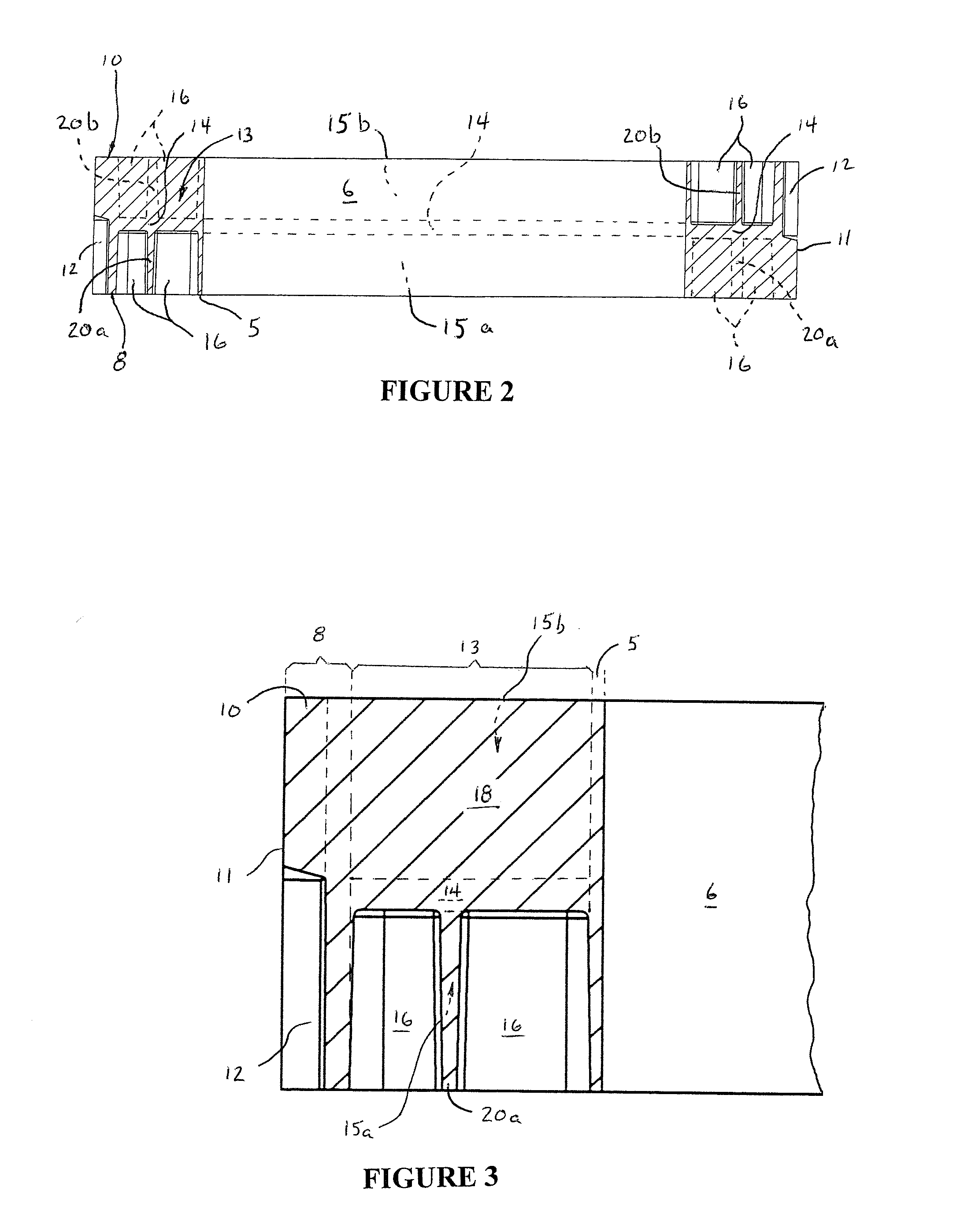
[0018]With reference to FIGS. 1 and 3, a central web 13 integrally connects the inner and outer hoop members 5 and 8. The central web 13 includes a disc shaped mid portion 14 and side portions 15a, 15b. Side portions 15a, 15b include elongated, ra...


PUM


Abstract

A non-pneumatic tire is provided with an annular reinforcing web that reduces the bending of compression spokes formed in the tire and reduces stresses and strains in the tire. The non-pneumatic tire includes an inner hoop member having an inner surface that defines the inner diameter of the tire, and an outer hoop member having a tread groove region that defines the outer diameter of the tire. A disc-shaped central web portion connects the inner and outer hoop members. A plurality of elongated, radially aligned cavities on either side of the central web defines integrally-formed compression spokes which connect the inner and outer hoop members. The annular reinforcing web is located on and affixed to either side of the central web portion and interconnects a mid portion of each spoke to a mid portion of the spokes on either side of it. Preferably, the annular reinforcing web is reinforced with fiber webbings on its outer side for added strength. The annular reinforcing web allows the tire to be made with less polyurethane material with no reduction in load carrying capability.

Description

FIELD OF THE INVENTION[0001]This invention generally relates to non-pneumatic tires having compression spokes, and is specifically concerned with a non-pneumatic tire having an annular, spoke-reinforcing web that reduces the bending of the spokes and reduces stresses and strains in the tire.BACKGROUND[0002]Off-the-road (OTR) vehicles, also known as off-highway vehicles, are commonly used in rugged terrain for mining, excavation, construction, military applications, and other heavy industrial applications. OTR vehicles include tractors, trucks, loaders, dozers, graters, excavators, etc., and may have operational weights as high as 380 to 460 tons. Typically such OTR vehicles have several inflatable tires made of rubber. These applications require that each tire have properties such as being puncture-resistant, able to carry relatively heavy loads, and good resistance to wear and tear. Conventional inflatable tires generally have short operational life spans of about six months. Furth...

Claims


Application Information

Patent Timeline
IPC IPC(8): B60C7/00
CPCB60C7/18B60C2007/107B60C7/22B60C7/107
Inventor PALINKAS, RICHARD L.LASKOWITZ, IANTOPAR, ANDREW
Owner CATERPILLAR INC
Learn More