
Composite metal wood club

a metal wood and club head technology, applied in the field of golf club head improvement, can solve the problems of inability to teach, high dependence on the accuracy of conventional clubs, and inability to achieve the effect of aligning teaching and teaching

Inactive Publication Date: 2006-12-28
ACUSHNET CO
View PDF99 Cites 37 Cited by
  • Summary
  • Abstract
  • Description
  • Claims
  • Application Information

AI Technical Summary

Benefits of technology

The design achieves a high and uniform coefficient of restitution across a larger area of the club face, enhancing ball velocity and distance while maintaining structural integrity, thus improving accuracy and forgiveness by aligning with the golfer's typical impact pattern.

Problems solved by technology

However, these environmental effects are beyond the control of the golf equipment manufacturer.
Furthermore, the accuracy of conventional clubs is highly dependent on impact location.
However, there is no teaching to align the coefficient of restitution of the golf club head to the ball impact pattern.

Method used


Image

  • Composite metal wood club
  • Composite metal wood club
  • Composite metal wood club

Examples


example

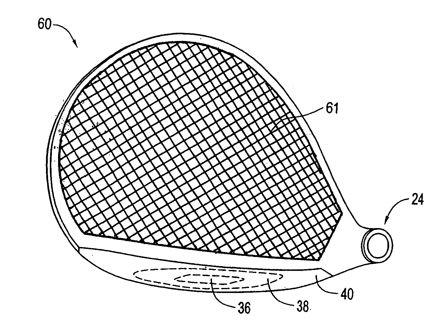
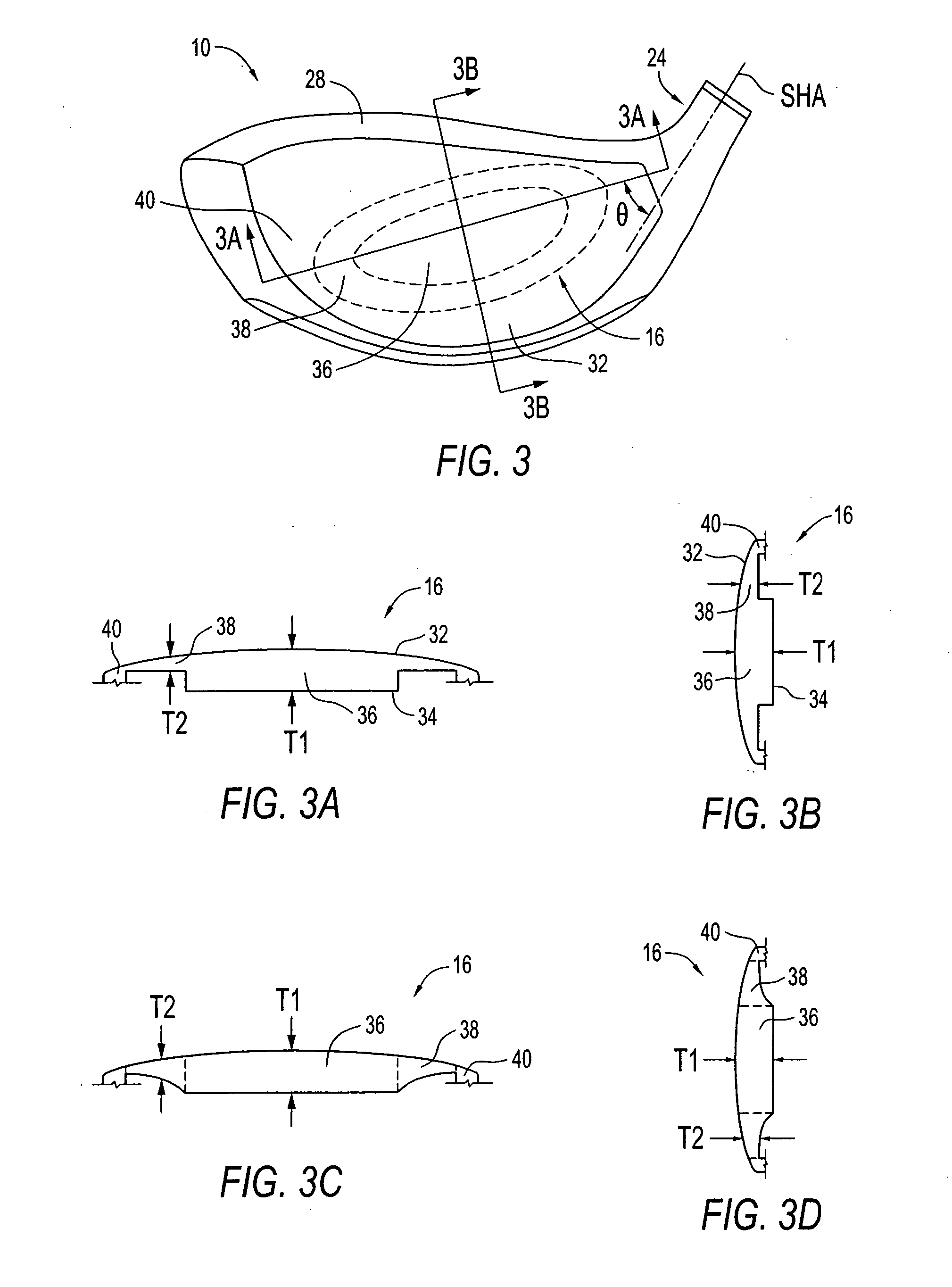
[0076] In this example, hitting face 16 has the following construction. The central zone 36 has a substantially parallelogram shape, as shown in FIG. 10(a), with a major axis measuring about 3 inches and a minor axis about 0.75 inches with a thickness T1, of about 0.120 inch. The central zone 36 has a concentric transition zone 37 with a similar shape as the central zone 36. The intermediate zone 38 surrounds the central and transition zones with a thickness T2 of 0.080 inch and comprises the remainder of the face hitting area. There is no perimeter zone 40 included in this example. The major axis of zone 36 substantially coincides with the major axis of zone 38, and these two major axes form angle theta (θ) of about 50° with the shaft axis. Furthermore, zones 36 and 37 comprise about 18% of the total face surface area. A single homogeneous material, preferably a titanium alloy, with a Young's modulus (E) of approximately 16.5×10⁶ lbs / in2 is used. In this example, the (FS1 / FS2) rati...


PUM

PropertyMeasurementUnit
frequencyaaaaaaaaaa
thicknessaaaaaaaaaa
velocityaaaaaaaaaa

Abstract

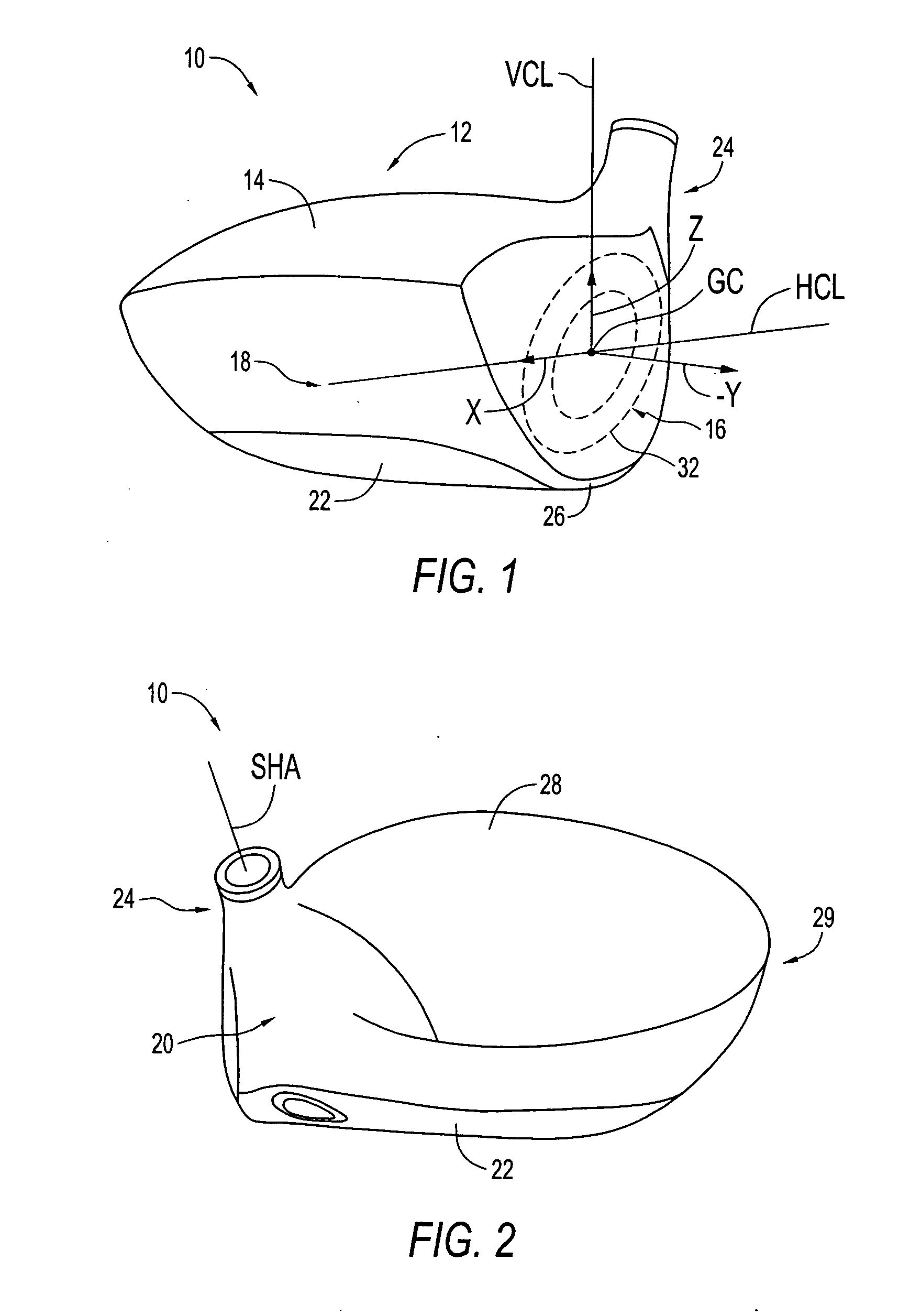
A metal wood golf club head adapted for attachment to a shaft, comprising of a body portion and a crown portion, each portion constructed of a different density material. Combining a high-density material in the body portion, with a low-density material in the crown portion, creates an ultra-low center of gravity relative to the geometric face center, resulting in higher launch angles and spin rate ratios. The material for the crown portion is preferably a composite. The crown portion comprises an inner surface layer of a vibration dampening material. The transverse surfaces of the crown and body portions creating a gap that is filled with a shock absorption material such as putty or a rubber based structural adhesive.

Description

CROSS-REFERENCE TO RELATED APPLICATION [0001] The present application is a divisional of U.S. patent application Ser. No. 10 / 799,118, filed on Mar. 12, 2004, which is a continuation-in-part of U.S. patent application Ser. No. 10 / 428,061, filed on May 1, 2003, and now U.S. Pat. No. 7,029,403, which is a continuation-in-part of U.S. patent application Ser. No. 09 / 551,771 filed on Apr. 18, 2000, and now U.S. Pat. No. 6,605,007. The disclosures of the parent patent applications are incorporated herein in their entirety.FIELD OF THE INVENTION [0002] The present invention relates to an improved golf club head. More particularly, the present invention relates to a golf club head with an improved striking face and improved shock absorption between the mating portions making up the body of the club head. BACKGROUND [0003] The complexities of golf club design are well known. The specifications for each component of the club (i.e., the club head, shaft, hosel, grip, and sub-components thereof)...

Claims


Application Information

Patent Timeline
Patent Type & Authority Applications(United States)
IPC IPC(8): A63B53/00A63B53/04A63B53/08A63B59/00G01N29/04
CPCA63B53/00A63B2209/02A63B53/08A63B59/0074A63B59/0092A63B2053/0408A63B2053/0412A63B2053/0416A63B2053/045A63B2053/0458A63B2053/0491A63B2059/0003A63B2209/00A63B2209/023G01N29/045G01N2291/014G01N2291/02854A63B53/0466A63B60/54A63B60/42A63B53/0412A63B53/0408A63B53/045A63B53/0416A63B53/0458A63B60/002A63B60/00
Inventor MEYER, JEFFREY W.RICE, SCOTT A.POYNOR, RAYMOND L.
Owner ACUSHNET CO
Learn More