
Ultrathin carbon fibers

Inactive Publication Date: 2006-03-23
HODOGAYA KAGAKU IND
View PDF12 Cites 39 Cited by
  • Summary
  • Abstract
  • Description
  • Claims
  • Application Information

AI Technical Summary

Benefits of technology

[0010] One aspect of the invention relates to ultrathin carbon fibers. Ultrathin carbon fibers in accordance with some embodiments of the invention may have physical properties suitable for use as fillers in composite preparations. They may have high dispersability in the matrix of the composite. They may have relatively straight shapes.
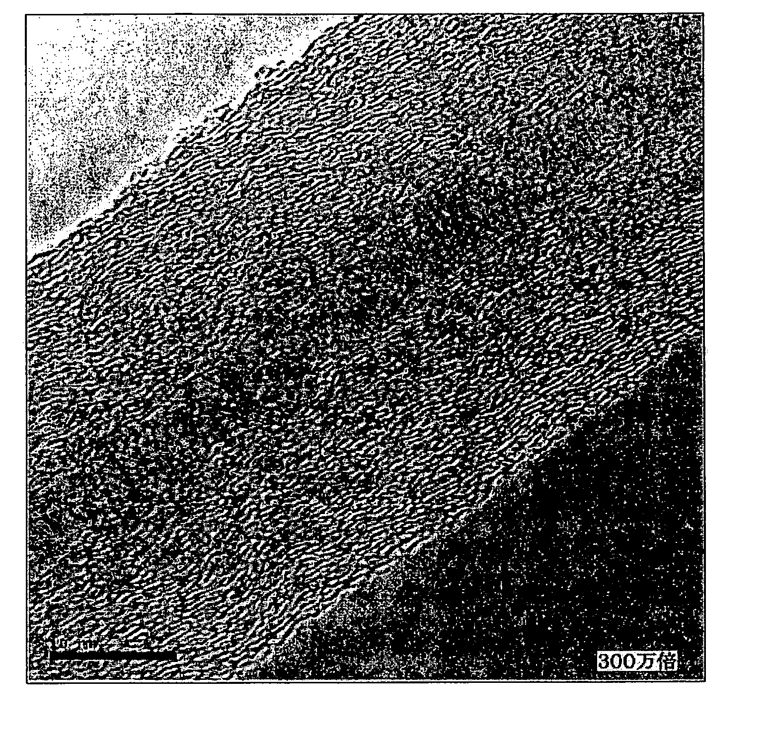
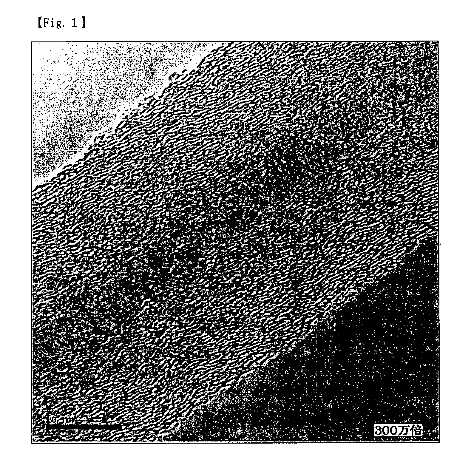
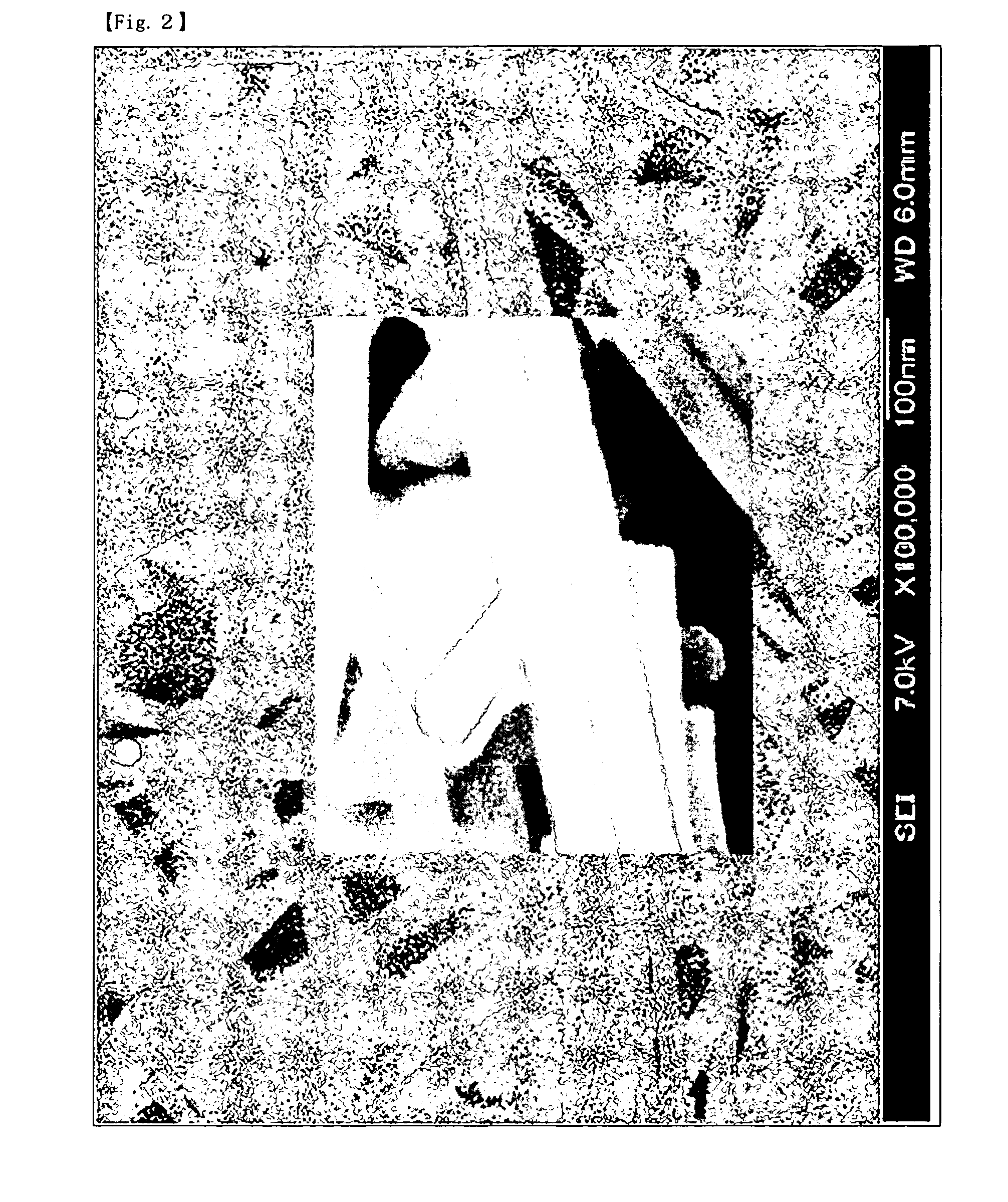
[0013] Inventors of the present invention have found that heat treatment of the ultrathin carbon fibers at high temperatures can reduce the magnitudes of the D bands and enhance the electrical conductivities of the ultrathin carbon fibers. The high-temperature treatment results in carbon fibers having polygonal cross sections (the cross section is taken in a direction orthogonal to the axes of the fibers). The high-temperature treatment also makes the resultant fibers denser and having fewer defects in both the layer stacking direction and the surface direction of the graphene sheets that comprise the carbon fibers. As a result, the carbon fibers have enhanced flexural rigidity (EI) and improved dispersability in a resin (or matrix material).
[0022] The ultrathin carbon fibers according to embodiments of the invention may have characteristics of high bending stiffness and sufficient elasticity. Thus, these fibers can restore their original shapes even after deformation. Therefore, the ultrathin carbon fibers according to embodiments of the present invention are less likely to intertwine in a state where the fibers are entangled with each other when they aggregate. Even if they happen to be entangled with each other, they can disentangle easily. Therefore, it would be easier to distribute these fibers in a matrix by mixing them with a matrix material because they are less likely to exist in an entangled state in the aggregate structure. Additionally, because carbon fibers according to some embodiments of the present invention have polygonal cross sections (in a direction orthogonal to the axis of the fiber), these carbon fibers can be more densely packed, and fewer defects will occur in both the stacking direction and the surface direction of the tubular graphene sheets that comprise the carbon fibers. This property gives these carbon fibers enhanced flexural rigidities (EI) and improved dispersability in the resin.
[0023] Furthermore, according to embodiments of the present invention, electrical conductivities of the carbon fibers may be improved by reducing defects in the graphene sheets that comprise the carbon fibers. Therefore, the carbon fibers according to embodiments of the present invention can provide better electrical conductivity when mixed in a matrix material.

Problems solved by technology

When these carbon fibers are analyzed with Raman spectroscopy, however, the D bands thereof may be large and many defects may be observed.
Furthermore, in some cases, the graphene sheets produced by the CVD processes may not fully develop, resulting in patch-like structures.

Method used


Image

  • Ultrathin carbon fibers
  • Ultrathin carbon fibers
  • Ultrathin carbon fibers

Examples


example 1

[0100] Using the CVD process, ultrathin carbon fibers are synthesized from toluene as a raw material. The synthetic system used is shown in FIG. 8.

[0101] The synthesis was carried out in the presence of a mixture of ferrocene and thiophene as the catalyst, and under a reducing atmosphere of hydrogen gas. Toluene and the catalyst were heated to 375° C. along with the hydrogen gas, and then they were supplied to the generation furnace to react at 1200° C. for a residence time of 8 seconds. The atmosphere gas was separated by a separator in order to use the atmosphere gas repeatedly. The hydrocarbon concentration in the supplied gas was 9% by volume.

[0102] The tar content as a percentage of the ultrathin carbon fibers in the synthesized intermediate (first intermediate) was determined to be 10%.

[0103] Next, the fiber intermediate was heated to 1200° C., and kept at that temperature for 30 minutes in order to effectuate the hydrocarbon separation. Thereafter, the fibers were subjecte...

example 2

[0106] The synthetic system used for this example is shown in FIG. 10. Benzene was used as the carbon source. Ferrocene and thiophene were used as the catalysts, which were added and dissolved in benzene. Then, the dissolved mixture was vaporized at 380° C., and the vaporized mixture was supplied to the generation furnace. The temperature in the generation furnace was 1150° C., and hydrogen gas was used as the atmosphere gas in the generation furnace. Residence time for the hydrogen gas and raw material gas was set to 7 seconds. The tar concentration in the carbon fibers (first intermediate), which were collected at the downstream side of the furnace supply gas, was found to be 14%.

[0107] Next, the carbon fibers (first intermediate) were subjected to heat treatment at 1200° C. for 35 minutes. After the heat treatment, the specific surface area of the resultant carbon fibers (second intermediate) were determined to be 33m2 / g. The ID / IG ratio, which was measured by Raman spectroscopy...

example 3

[0109] The ultrathin carbon fibers obtained in Example 1 was analyzed with an X ray diffraction. For comparison, a graphite sample was also subjected to X ray diffraction analysis. The X ray diffraction patterns obtained from these determinations are shown in FIG. 6. However, because the peak intensity for the ultrathin carbon fibers of Example 1 was very weak, the trace for the ultrathin carbon fibers was amplified 10 times for comparison with that for graphite.

[0110] From the comparison, it was found that both samples had a peak corresponding to the diffraction of the (110) face lying at approximately 77°. It was also found that the graphite sample had a peak corresponding to the diffraction of the (112) face lying at approximately 83°, while the sample of the ultrathin carbon fibers of Example 1 did not have such a peak. Therefore, this result shows that the ultrathin carbon fibers according to the present invention do not have a regular, three-dimensional structure like that of...


PUM


Abstract

An ultrathin carbon fiber having two or more tubular graphene sheets layered is disclosed. The tubular graphene sheets has a polygonal cross section in a direction substantially orthogonal to the axis of the ultrathin carbon fibers, a diameter of the fiber is 15 to 100 nm, an aspect ratio of the carbon fiber is not more than 105, and ID / IG of the carbon fiber as determined by Raman spectroscopy is not more than 0.2.

Description

CROSS-REFERENCE TO RELATED APPLICATIONS [0001] This application claims priority of Japanese Patent Applications Nos. 2004-103083, 2004-268878, and 2004-347384, filed on Mar. 31, 2004, Sep. 15, 2004, and Nov. 30, 2004, respectively. BACKGROUND OF THE INVENTION [0002] 1. Technical Field [0003] This invention relates to ultrathin carbon fibers comprising tubular laminates of ultrathin carbon sheets. Particularly, this invention relates to the ultrathin carbon fibers which are suitable for use as a filler to be added to resin or the like. [0004] 2. Background Art [0005] Carbon fibers are well known in the art. These are carbons having fibrous appearance. Some of these are known as ultrathin carbon fibers, which may be classified by their diameters and have received wide attention. The ultrathin carbon fibers may also be referred to as, for instance, vapor phase grown carbon fiber, carbon nanofiber, carbon nanotube, etc. [0006] Among carbon fibers, the carbon nanotubes are those typicall...

Claims


Application Information

Patent Timeline
IPC IPC(8): D01F9/12B32B9/00C01B31/02D01F9/127
CPCB82Y30/00B82Y40/00Y10T428/30D01F9/127C01B31/0233C01B32/162
Inventor ENDO, MORINOBUTSUKADA, TAKAYUKIMUNEKANE, FUMINORIOSATO, KAZUHIRO
Owner HODOGAYA KAGAKU IND
Learn More