Method for continuously forming structural member

a structural member and continuous technology, applied in the direction of girders, efficient propulsion technologies, other domestic articles, etc., can solve the problems of deterioration of flexural rigidity in the low stress area, inferior production efficiency of prior art methods, and high cost, so as to minimize undulation of fibers and high flexural elastic modulus

Active Publication Date: 2008-05-01
JAMCO
View PDF6 Cites 35 Cited by
  • Summary
  • Abstract
  • Description
  • Claims
  • Application Information

AI Technical Summary

Benefits of technology

[0052]The present invention further aims at providing a method for forming structural members having high flexural rigidity in a low stress area while minimizing the “fluctuation” of the fiber caused during the forming process.
[0061]The application of a continuous adhesive-bonding method enables to vary the curvature of the structural member arbitrarily in mid course, to manufacture a long structural member, and to perform heating and pressing required to bond the structural member without fail.
[0065]A method is adopted to apply initial tension to the fibers receiving the load of stress as structural member and straightening the fibers as a means to eliminate fluctuation of the fibers caused during forming of the composite member and create a beam member having high flexural rigidity in a low stress area.
[0069]By applying a combination of basic means K−1 and basic means K−2 of the present invention, it becomes possible to ensure a method for forming a structural member being bent with a given curvature, a hollow structural member, a structural member being curved with the curvature varied in the middle, and a torsional structural member with a given torsion.
[0070]Furthermore, by further applying basic means K−3 in addition to the above, it becomes possible to provide a method for forming a structural member having a high flexural elastic modulus while minimizing the undulation of fibers caused during the forming process.

Problems solved by technology

However, the prior art method has inferior production efficiency and high costs, since the method requires a large-scale autoclave device 600 and a large mold (molding jig) 620, requires molding processes involving manpower called lay-up and set-up, and produces only a limited number of products in a single molding process.
In addition, the method has a drawback in that the influence of thermal expansion coefficient that differs according to the material causes undulation (fluctuation) of the carbon fibers F1 that constitute the fabricated structural member, by which both the strength and elastic modulus of the member are deteriorated, and as a result, the flexural rigidity in the low stress area is deteriorated.
On the other hand, if compressive load is applied, the buckling of the fiber is increased, so that the stress-strain diagram shows a low elastic modulus as illustrated in portion C of FIG. 18, which finally results in buckling.
One means for solving the problem of fluctuation is the use of a mold formed of a special metal material having zero thermal expansion coefficient called an inver instead of the mold made of aluminum alloy, but there are drawbacks in that the material is expensive, the processing thereof is difficult, and the thermal conductivity is as small as stainless steel, which elongates the time required for the heating step.
The method is advantageous in that it has high productivity, and is suitable for manufacturing panel products, but due to limitations regarding the press mold and the pressurizing direction, the method is not suitable for forming structural members having a complex cross-sectional shape, or for forming long structural members.
When manufacturing a large-sized product, since it is difficult to ensure the surface accuracy of the press mold, it is difficult to manufacture an accurate structural member.
When steel having low thermal expansion coefficient is used to form the press mold of the hot press, thermal expansion of the press mold will not affect the product greatly, however, thermal contraction of resin will inevitably affect the product.
However, the method cannot be applied to form a structural member having a complex cross-sectional shape or a structural member having high quality.
However, there is a limitation to the cross-sectional shape of the member to be formed due to limitations regarding the shapes of molds for heating and pressing the material and the limitations regarding pressing direction.
Structural members having intense curvature, structural members having a hollow structure and structural members having torsion are demanded as structural members of aircrafts, but such structural members are difficult to form using the ADP forming method.
However, the cross-sectional shapes and curvatures of the members to be formed are still limited.
The structural members using advanced composite materials are light-weight and have high strength, but the method for forming the same are not yet developed, so the advanced properties of the materials are not fully utilized.

Method used


Image

  • Method for continuously forming structural member
  • Method for continuously forming structural member
  • Method for continuously forming structural member

Examples


second embodiment

of the Present Invention

[0142]A second embodiment of the present invention is illustrated in FIG. 7-1, related to a method for manufacturing a curved beam 400 of a carbon fiber composite material curved with a given curvature and having a hat-shaped cross-section (hat section) to be applied for example to a body frame of an aircraft.

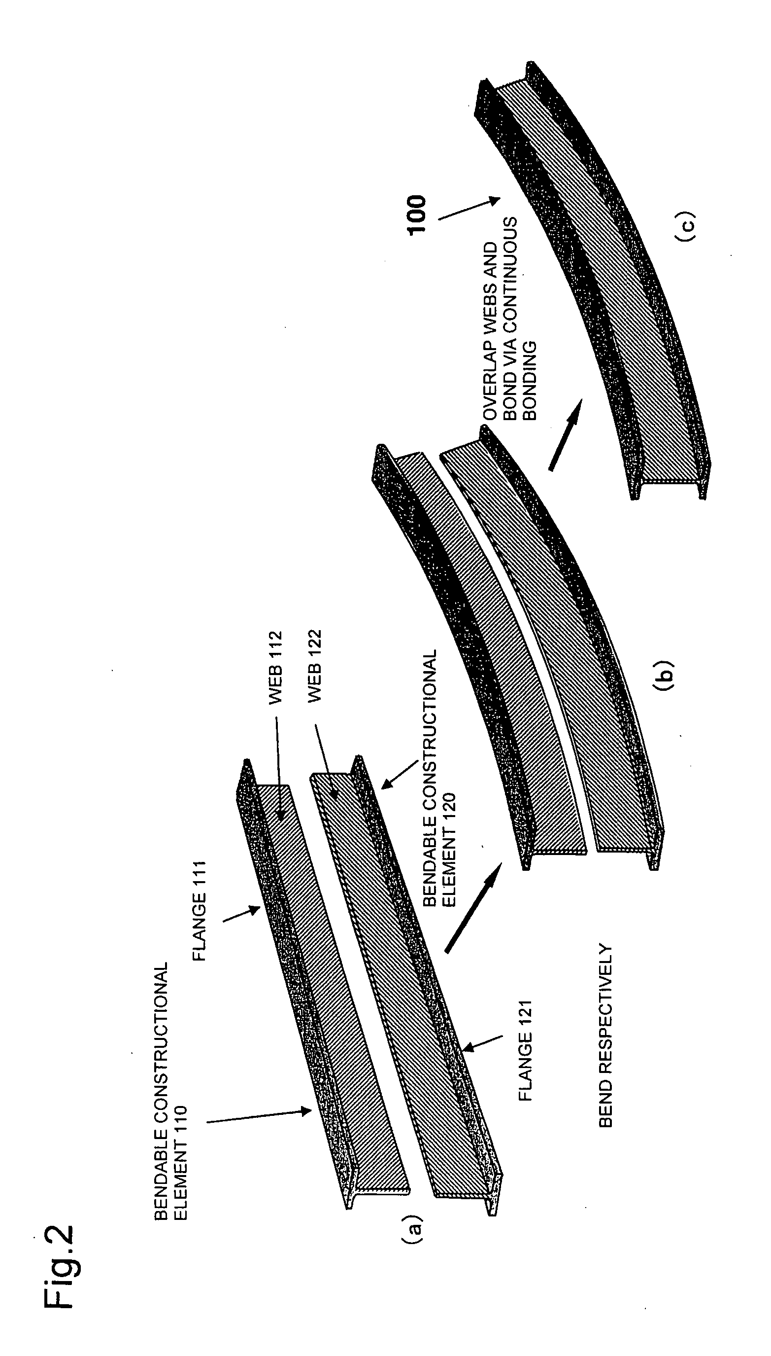
[0143]In order to manufacture a constructional element 400 having a hat section, the “basic means K−1” of the present invention is applied to form three constructional members, a channel-shaped constructional element 410 and two constructional elements 420 and 430 having an angled cross-section, and then the “basic means K−2” is applied to perform adhesive bonding.

[0144]Each of the constructional elements 410, 420 and 430 are manufactured via an ADP method, which is formed in a long and bent state, and prepared to be bonded.

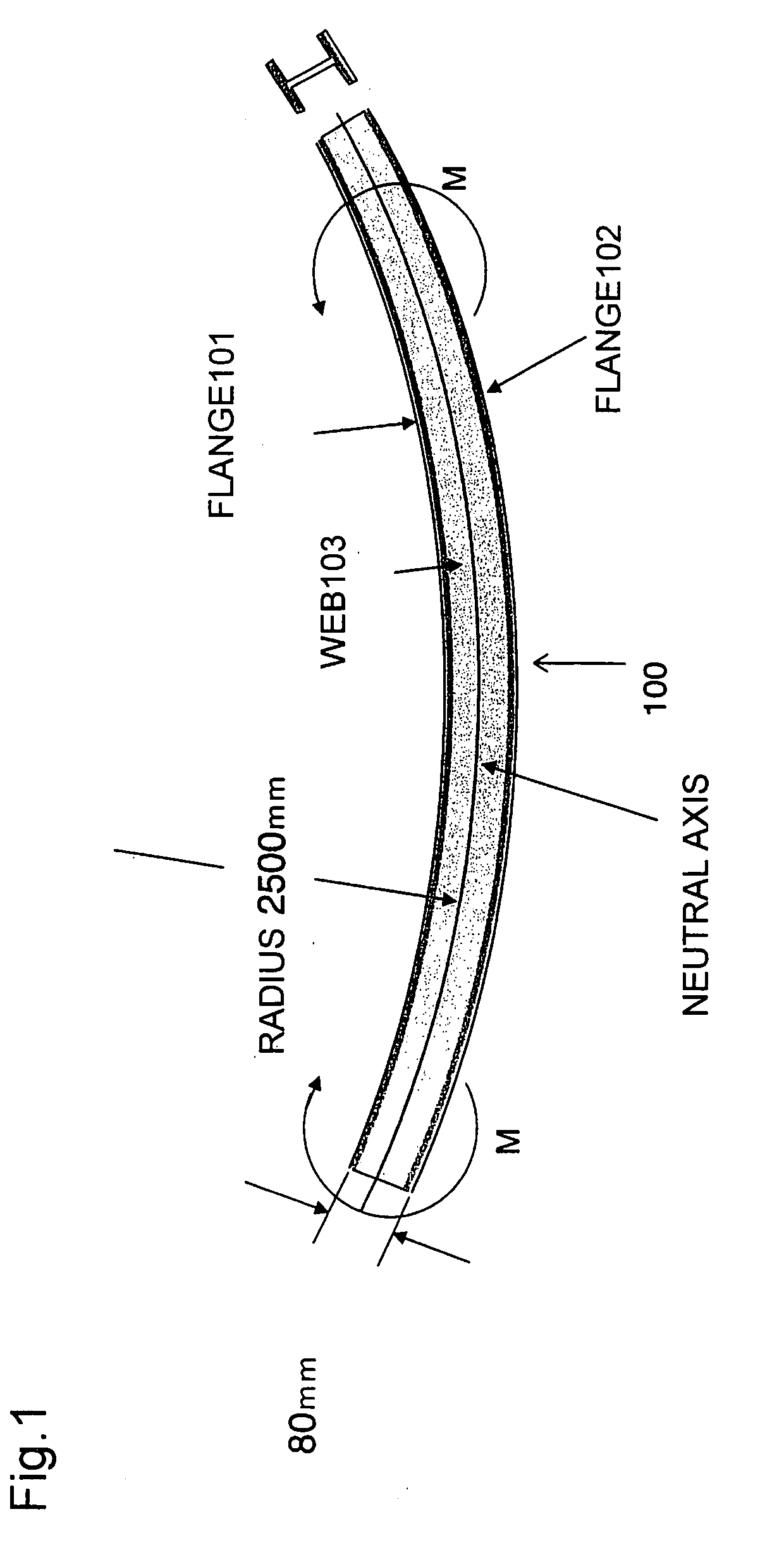
[0145]When a bending moment is applied to a beam member 400 having a hat section, sides 401, 404 and 405 constituting the flange of ...

fourth embodiment

of the Present Invention

[0177]The fourth embodiment of the present invention describes a method for manufacturing a stringer of a rear fuselage of an aircraft.

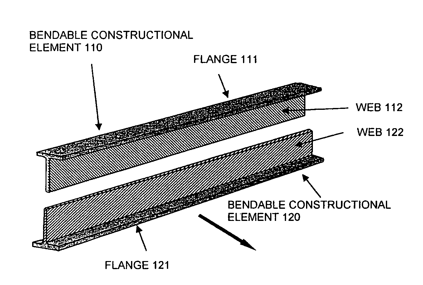
[0178]As shown in FIG. 13, a fuselage stringer 700 of an aircraft functions to receive load of tensile / compressive force (especially compressive force) that the outer panel of the body receives, so that force is transferred from a flange 701 to a web 702. Therefore, the flange 701 of the stringer 700 must endure shear force, while the web 702 must endure tensile / compressive force.

[0179]Since the rear fuselage of an aircraft is narrowed toward the tail, the stringers supporting the outer panel of the body are formed as structural members with curvature, and the curvatures of each member differ according to the mounting position of the members.

[0180]In the prior art, the metallic rear fuselage stringer is formed by manufacturing a straight stringer and providing via secondary plastic deformation process the required curvatures c...


PUM

PropertyMeasurementUnit
temperatureaaaaaaaaaa

Abstract

The invention provides an improved method for forming a composite material mainly composed of carbon fiber. It is difficult to form an H-shaped structural member formed of a prepreg material having carbon fiber fabric impregnated with epoxy resin into a member having curvature. Thus, the structural member is divided into two bendable constructional elements 110 and 120, which are bent to given curvature then adhesively-bonded to form a structural member having curvature.

Description

[0001]The present application is based on and claims priority of Japanese patent application No. 2006-295219 filed on Oct. 31, 2006, the entire contents of which are hereby incorporated by reference.BACKGROUND OF THE INVENTION[0002]1. Field of the Invention[0003]The present invention relates to a method for continuously forming a structural member using a composite material.[0004]2. Description of the Related Art[0005]One typical method for forming a structural member using a composite material mainly composed of carbon fiber is the forming method using an autoclave device.[0006]FIG. 16 illustrates the outline of the manufacturing method using an autoclave device 600, wherein the composite material used in the autoclave forming method is a material called a carbon fiber / epoxy prepreg, in which a carbon fiber fabric is impregnated with epoxy resin.[0007]In this method, nitrogen gas is filled in a can 600 of the autoclave device, and the pressure and temperature of nitrogen gas is rai...

Claims


Application Information

Patent Timeline
Patent Type & Authority Applications(United States)
IPC IPC(8): B32B1/04B29D99/00
CPCB29C35/02Y10T156/101B29C66/1122B29C66/524B29C66/545B29C66/547B29C66/721B29C66/8322B29C66/919B29C66/929B29C66/939B29C66/949B29C70/50B29C70/56B29K2063/00B29K2307/00B29L2031/003B29L2031/3082E04C3/28E04C3/29B29C65/5057B29C66/934B29C65/5092Y02T50/433B29C66/9141B29C66/91443B29C66/91645B29C65/4835B29C66/92921B29C65/00B29C66/7212B29C66/72141B29C66/8122B29C66/81261B29D99/0003B29C66/112B29C66/1282B29C66/12841B29C66/131B29C66/1312B29C66/8242Y02T50/40B29K2307/04B29K2905/12
Inventor UMEDA, KATSUHIKOASARI, KAZUMIKURIYAMA, SHUNTARO
Owner JAMCO
Why Eureka
Try Eureka