Electrostatic comb drive actuator, and optical controller using the electrostatic comb drive actuator

a technology of electrostatic comb drive and actuator, which is applied in piezoelectric/electrostrictive/magnetostrictive devices, microelectromechanical systems, instruments, etc., can solve the problem of inability to extend the range of adjustable attenuation

Inactive Publication Date: 2005-03-10
MORITEX CORP +1
View PDF2 Cites 42 Cited by
  • Summary
  • Abstract
  • Description
  • Claims
  • Application Information

AI Technical Summary

Benefits of technology

[0030] In the case where the optical element is a shutter, if return light-preventing V-shaped grooves are formed...

Problems solved by technology

However, in this suspension and support structure, since the working section can be moved only to such an extent that the springs can be elastically deformed in the leng...

Method used


Image

  • Electrostatic comb drive actuator, and optical controller using the electrostatic comb drive actuator
  • Electrostatic comb drive actuator, and optical controller using the electrostatic comb drive actuator
  • Electrostatic comb drive actuator, and optical controller using the electrostatic comb drive actuator

Examples


Embodiment Construction

[0039] The detail of this invention is described below as an example in reference to the attached drawings.

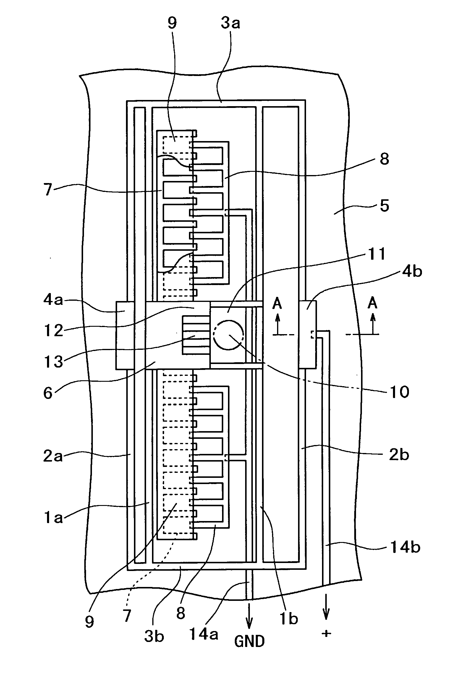
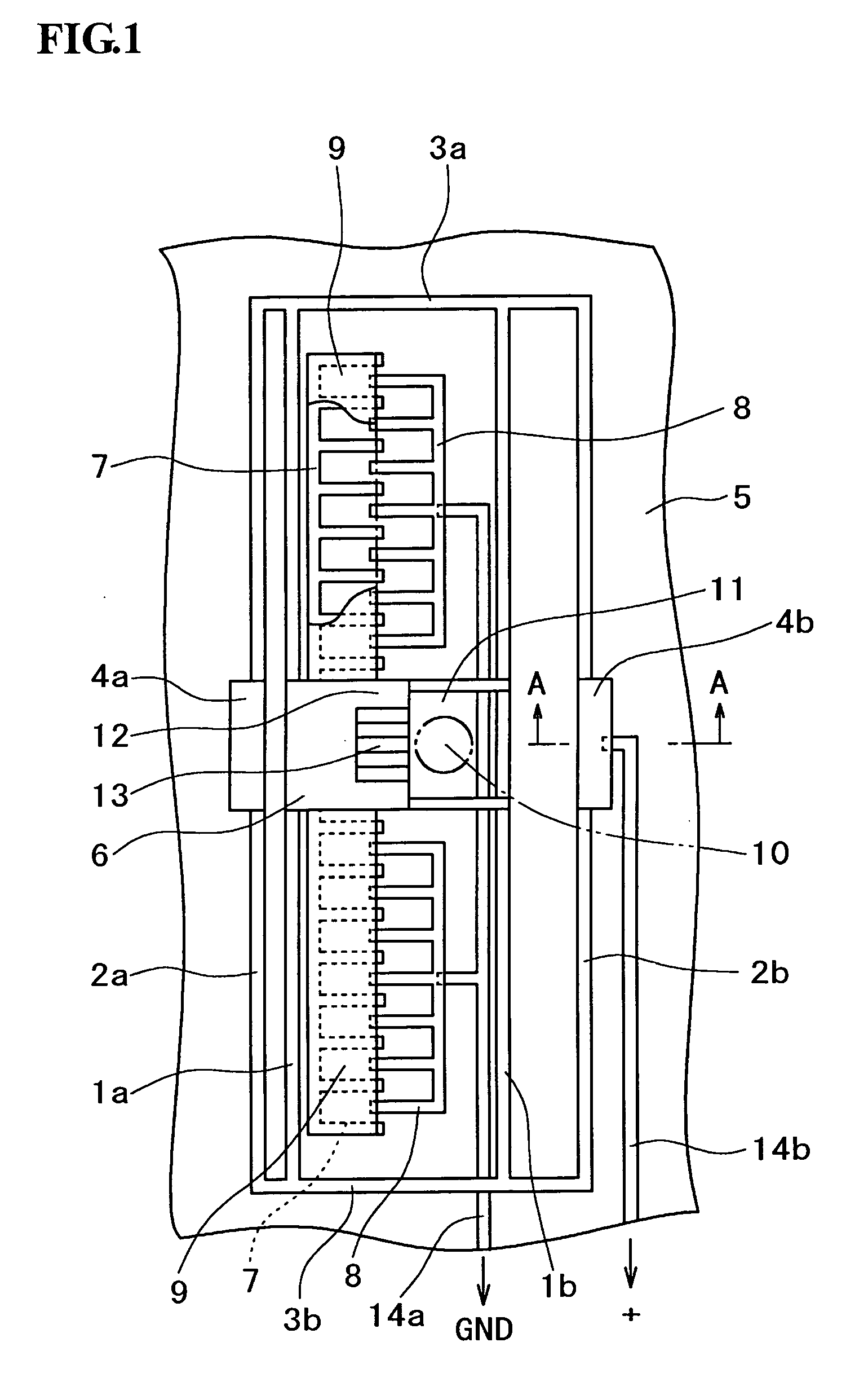
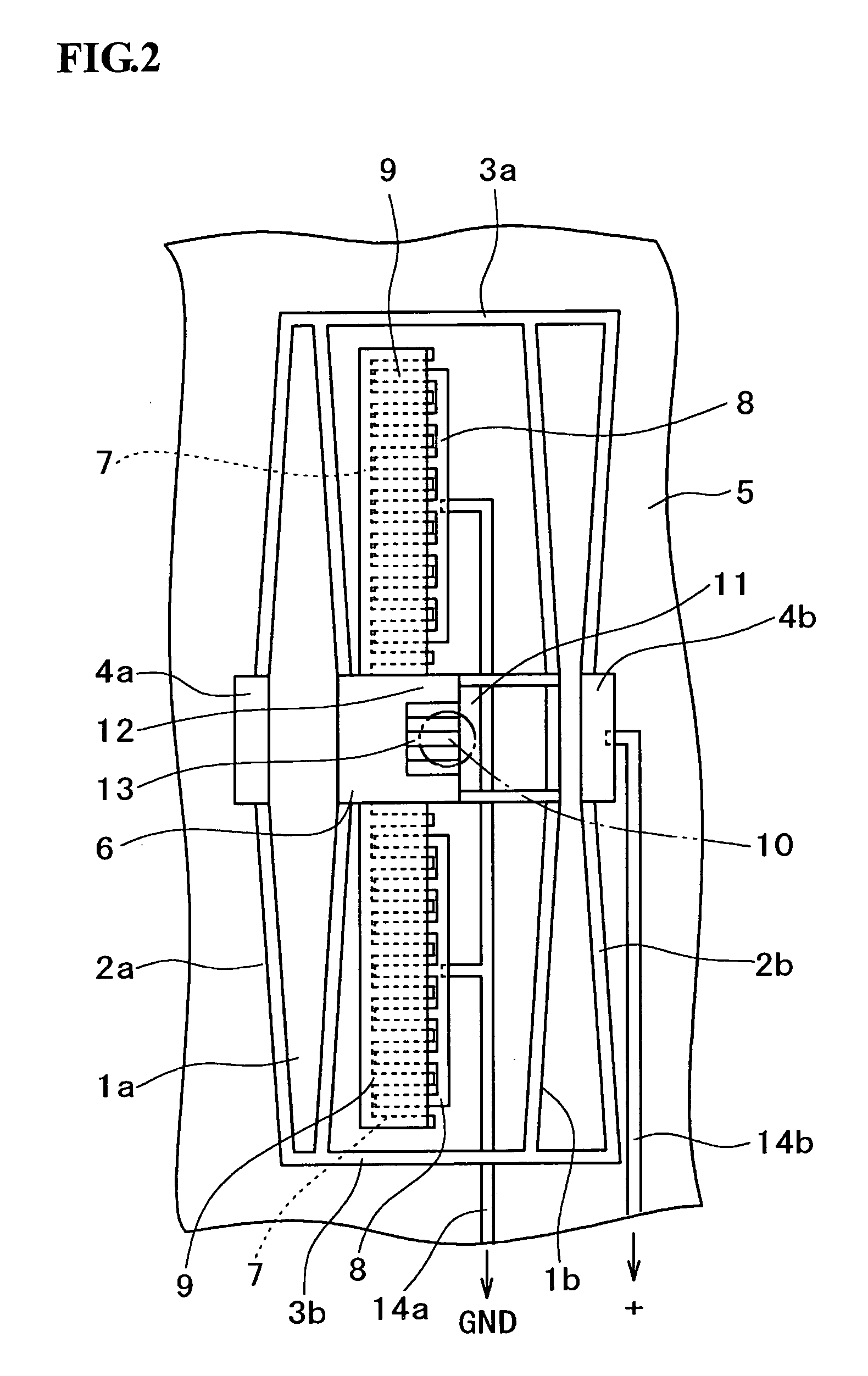
[0040]FIGS. 1 and 2 are plan views showing a VOA as an optical controller comprising the electrostatic comb drive actuator of this invention. FIGS. 3 and 4 are perspective views showing the constitution in a simplified and typified manner.

[0041] Symbols 1a and 1b denote a plurality of, in this case, a pair of inner suspended elastic beams disposed in parallel to each other, and outside them, outer suspended elastic beams 2a and 2b are disposed in parallel to each other. The ends of the inner suspended elastic beams 1a and 1b and the outer suspended elastic beams 2a and 2b on both sides are connected with end connecting beams 3a and 3b.

[0042] The outer suspended elastic beams 2a and 2b are supported at support portions 4a and 4b at their centers on a board 5. Furthermore, the inner suspended elastic beams 1a and 1b are connected with each other at their centers by a working s...


PUM


Abstract

An electrostatic comb drive actuator, characterized in that plural outer suspended elastic beams 2a and 2b are disposed in parallel to and outside plural inner suspended elastic beams 1a and 1b disposed in parallel to each other; the ends of the inner suspended elastic beams and the outer suspended elastic beams on both sides are connected with end connecting beams 3a and 3b; the outer suspended elastic beams are supported at their centers on a board 5; the inner suspended elastic beams are connected with each other at their centers by means of a working section 6; a movable comb electrode 7 is supported on the working section; and a fixed comb electrode 8 is supported on the board.

Description

FIELD OF THE INVENTION [0001] The present invention relates to an electrostatic comb drive actuator, particularly an electrostatic comb drive actuator using the micro-electro-mechanical system technology, and also to an optical controller using the electrostatic comb drive actuator. BACKGROUND OF THE INVENTION [0002] In recent years, owing to the development of the micro-electro-mechanical system (MEMS) technology applying the semiconductor microfabrication technology, micro-electro-mechanical systems are used in various application fields. For example, the application of MEMS to optical technology, i.e., optical MEMS shows a remarkable progress in recent years, and small-sized high-performance high-function optical controllers for performing optical operations by means of mechanical motions are being realized. [0003] For example, U.S. Pat. No. 6,459,845 describes a variable optical attenuator (VOA) in which a shutter or mirror is movably installed between an optical fiber of transm...

Claims


Application Information

Patent Timeline
IPC IPC(8): B81B3/00G02B26/02
CPCB81B3/0037B81B2201/033B81B2203/051B81B2203/0136B81B2201/045
Inventor WATANABE, SHIN-ICHIROHORIO, KOJIMUTA, KENICHIESASHI, MASAYOSHI
Owner MORITEX CORP
Why Eureka
Try Eureka