[0030]Optimally loaded wind turbines can harvest sustainable mechanical power from highly variable winds. My present invention generator can convert highly variable shaft power to
usable electric power having regulated current and voltage. An embodiment for
wind power efficiently generates electric power that is proportional to the third power of speed, over a very broad speed range. It would greatly enhance
power quality and produce approximately double the prior art generator electric power energy yields from wind, by harvesting electric power during prevalent low wind speeds and continue to harvest electric
power over the entire
wind speed spectrum.
[0031]Moreover, its
scalability facilitates optimal wind
turbine loading, without incurring re-tooling expenses to achieve a broad
power rating range. The importance of optimal loading is best explained by considering extreme mismatch between a wind turbine and the generator it drives: Potential wind turbine output power is not substantially harvested if generator
power capacity is so slight that the wind turbine coupled to it has minuscule torque load. Conversely, output power is zero when generator loading is so high that it causes the wind turbine to stall. Those versed in the art of generating electric power from wind turbines know that potential wind turbine output power as a function of
wind speed is a continuous function, whose maximum power yield corresponds to optimal loading, facilitated by matching a generator to the wind turbine that can best drive it, over a broad
wind speed range. Said speed and load scaling and matching is a primary attribute of the present invention.
[0032]Considering another alternate embodiment, a generator that can convert variable-speed pedal power from a recumbent cyclist, in an
electric vehicle, that charges onboard batteries and thereby extends the practical vehicle range, while affording a healthy exercise option, is an example of an alternate embodiment of the present generator invention. Considering yet another alternate embodiment example, fitness exercise gyms, having
exercise equipment connected to such generators, could meet their onsite power needs and perhaps even return power to a utility grid. Considering another application,
wave motion and
water flow from rivers and streams is variable. Nevertheless, locations exist where the present generator invention can afford an opportunity for environmentally responsible electric power therefrom.
[0033]Accordingly, a general objective of the present invention is to provide a generator, which does not require speed-up gearing to increase its shaft speed, and which has zero cogging torque. A main objective is to provide a generator, which can efficiently generate better quality electric power, with controlled current and voltage, especially at very low shaft speeds, over a very broad speed range. It also should facilitate optimal wind turbine loading. Its shaft would preferably be powered by wind turbines having means to limit maximum speed by varying
blade pitch or deflecting wind from the blades when a desired maximum speed is reached. When that is not feasible, a friction
brake may be added to limit turbine shaft speed.
[0036]Another objective is to provide a variable speed generator responsive to user selected torque settings, which can efficiently generate electric power at requisite voltage, from
human power, to pedals driven by a driver who would benefit from recumbent
cycling exercise. This would also increase driving distance range and thereby appreciably enhance ultra-light electric road vehicles having on-board batteries and a plug-in charger, photovoltaic exterior top surfaces, and brushless regenerative ultra-efficient motors in wheels, which include radial-compliant springs to hold relatively large
diameter tire rims. Such an electric road vehicle is one of many examples of practical, sustainable, environment-responsible, low-cost transportation means that would be enhanced by the present invention generator.
[0041](1)
Rotor magnets to provide a rotating nearly sinusoidal
field pattern to each phase of a coreless stator winding, with
relative motion therebetween, as the rotor
spins, without magnetically
cycling iron or magnets in their closed
magnetic flux paths, and thus not incurring
magnetic hysteresis losses and cogging torque.(2) Rotor magnet sensors, responsive to
rotor angle, each aligned with a respective stator conductor phase, to each provide an alternating nearly sinusoidal feedback
signal responsive to
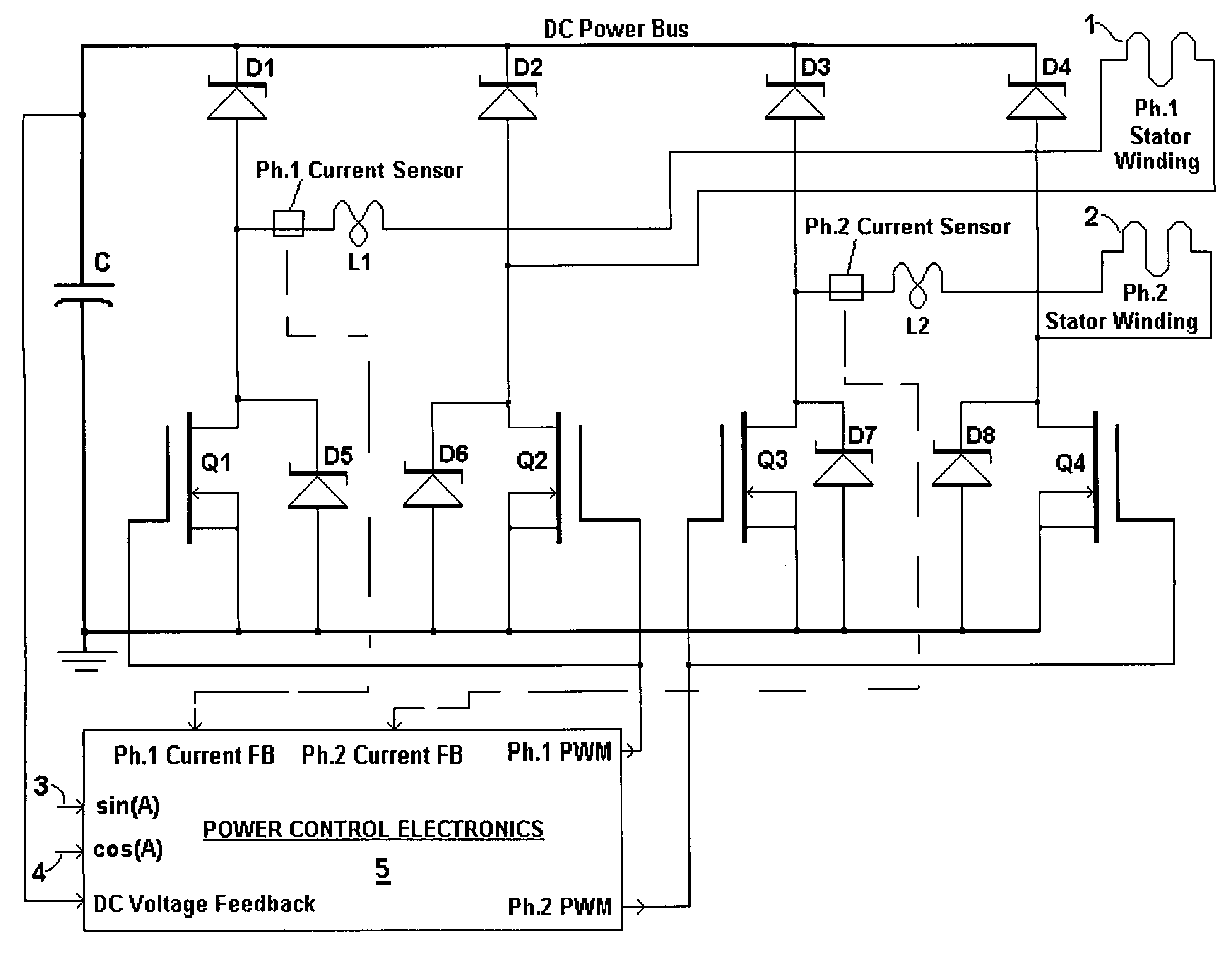
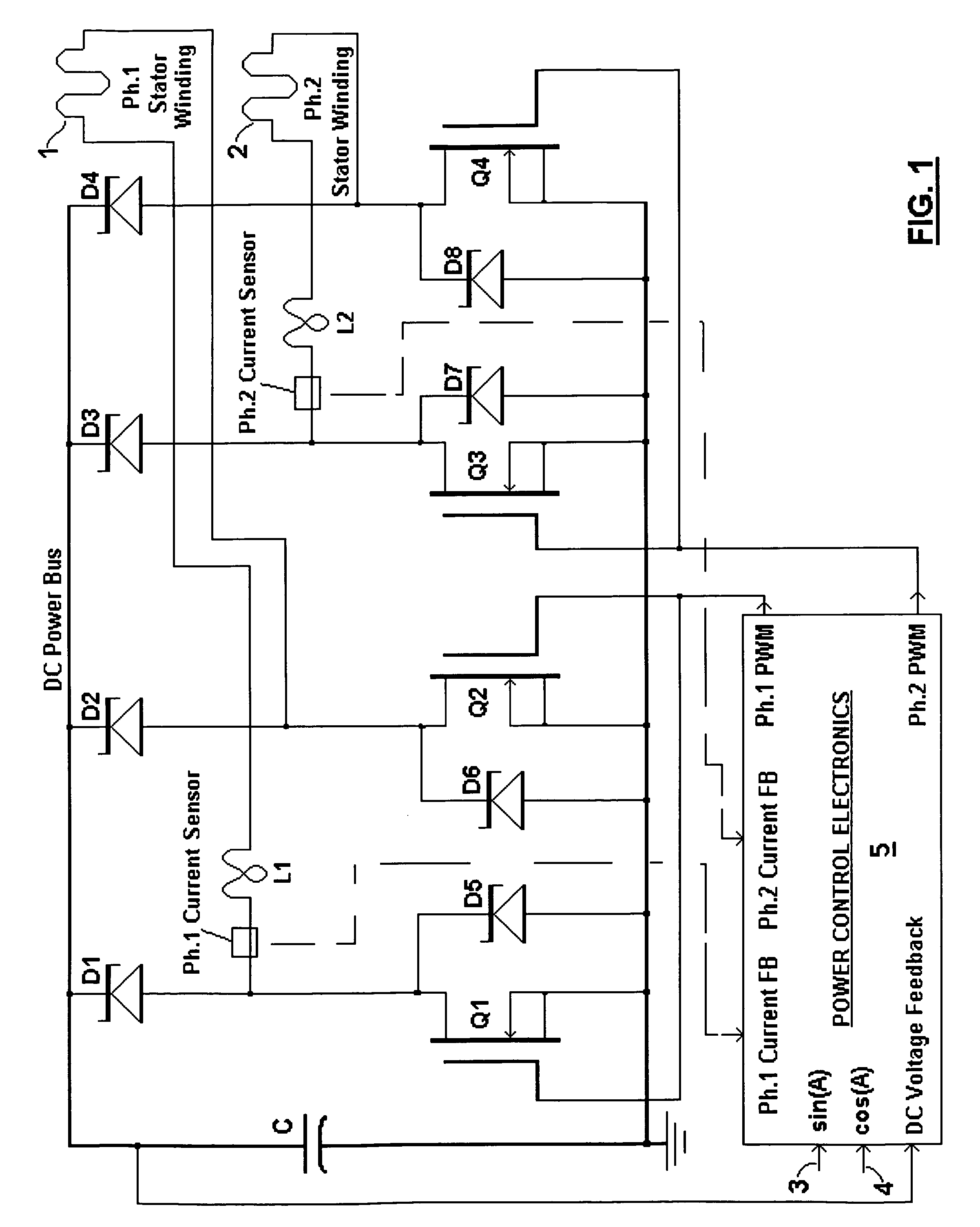
rotor angle, used by integral electronics to control respective stator winding current.(3) Current sensors, to each provide a respective current feedback
signal over a very broad
dynamic range, corresponding to respective stator conductor current.(4)
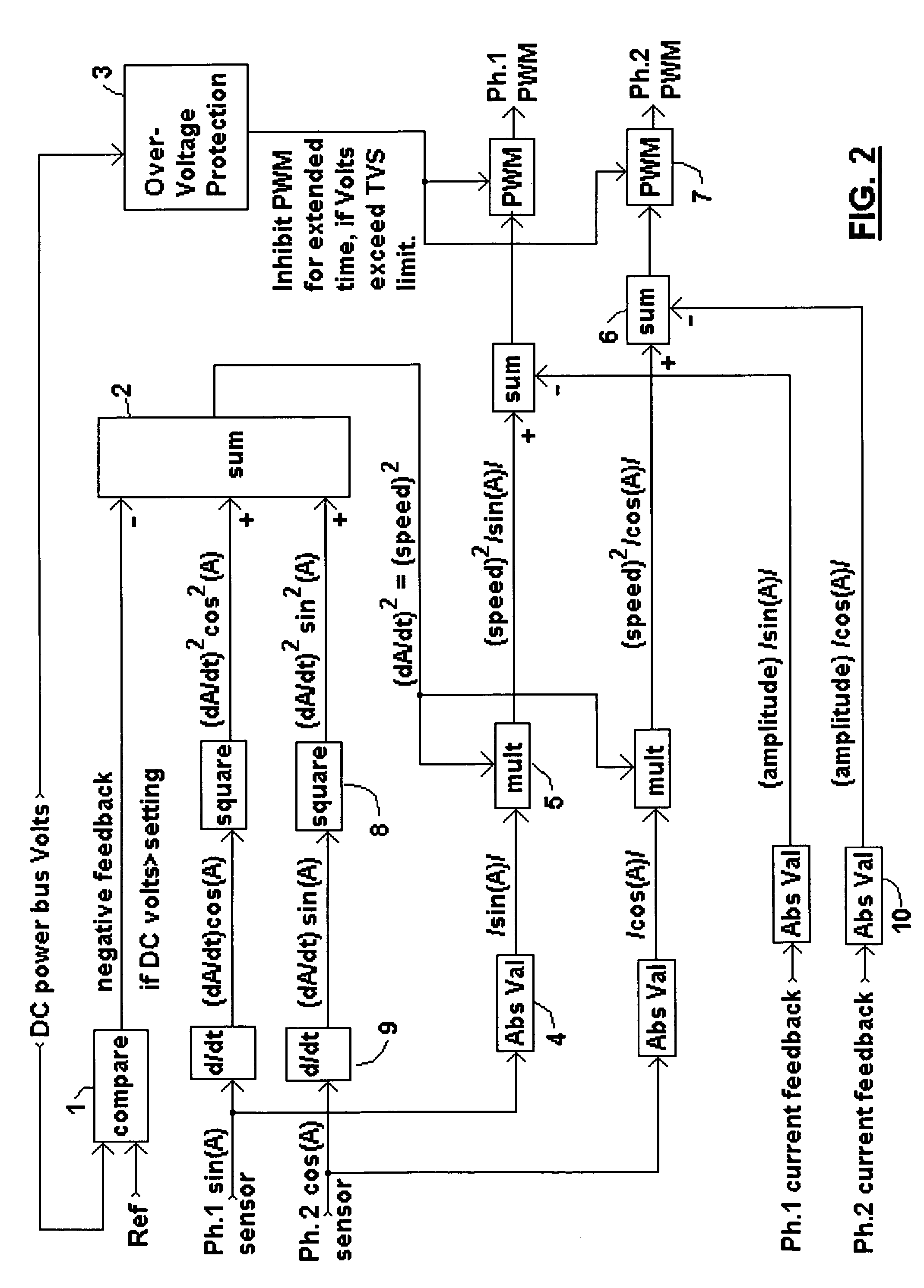
Signal processing electronics, normally responsive to the rotor magnet and current sensors, and to
DC voltage feedback, to control stator current by PWM and thereby efficiently generate regulated
DC current and voltage, from wide speed range rotational power, by boost regulation (fly-back
inductor and free-wheeling
diode pulse current generation and rectification filtered by high-frequency pulse averaging capacitors). This enables useful DC power generation at requisite
DC voltage over a very broad speed range.(5) Scalable combinations of these elements, that facilitate a wide power range, without need for many different size parts and the tooling required to manufacture them.

