Method for sensorless estimation of rotor speed and position of a permanent magnet synchronous machine

a synchronous machine and rotor technology, applied in the direction of motor/generator/converter stopper, dynamo-electric converter control, instruments, etc., can solve the problems of current ripple, torque ripple, high cost of low-cost frequency converter components, etc., to achieve stable operation, stable estimation, and wide speed range

Active Publication Date: 2010-07-20
ABB (SCHWEIZ) AG
View PDF7 Cites 27 Cited by
  • Summary
  • Abstract
  • Description
  • Claims
  • Application Information

AI Technical Summary

Benefits of technology

[0018]An adaptive observer as disclosed in [12] A. Piippo, M. Hinkkanen, and J. Luomi, “Analysis of an adaptive observer for sensorless control of PMSM drives,” in Proc. IEEE IECON'05, Raleigh, N.C., November 2005, pp. 1474-1479, is used for the rotor speed and position estimation, and for estimating the stator current. A modified high-frequency (HF) signal injection is used at low speeds to stabilize the estimation. The method of the invention enables stable operation in a wide speed range.

Problems solved by technology

Hall-effect sensors, which are commonly used for this purpose, are expensive components in low-cost frequency converters.
In addition, deviations in the gains between current sensors of different phases may cause current ripple and, consequently, torque ripple.
Some of the previous methods require modification of the inverter switching pattern [2], [7], which results in voltage and current distortion and additional losses.
The benefit of rejecting the switching frequency and its subharmonics by the synchronized sampling is also lost with a variable sampling interval, and additional compensation algorithms have to be applied.
One of the problems with the above is that the traditional signal injection does not necessarily give sufficient results in connection with DC-link current measurements.
This is due to the fact that DC-current measurement gives samples from the output phase currents rather irregularly, which leads to a situation where the high-frequency current originating from the injected voltage cannot be reliably determined.

Method used


Image

  • Method for sensorless estimation of rotor speed and position of a permanent magnet synchronous machine
  • Method for sensorless estimation of rotor speed and position of a permanent magnet synchronous machine
  • Method for sensorless estimation of rotor speed and position of a permanent magnet synchronous machine

Examples


Embodiment Construction

1 Control System

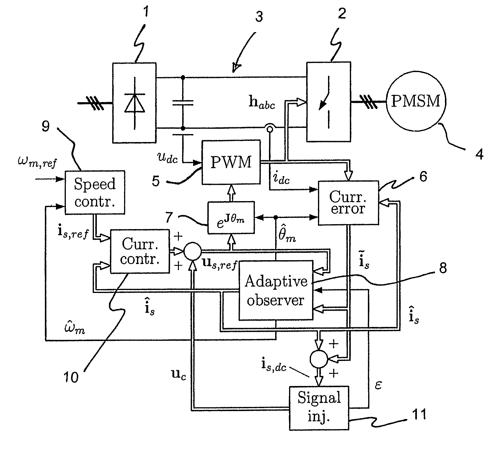
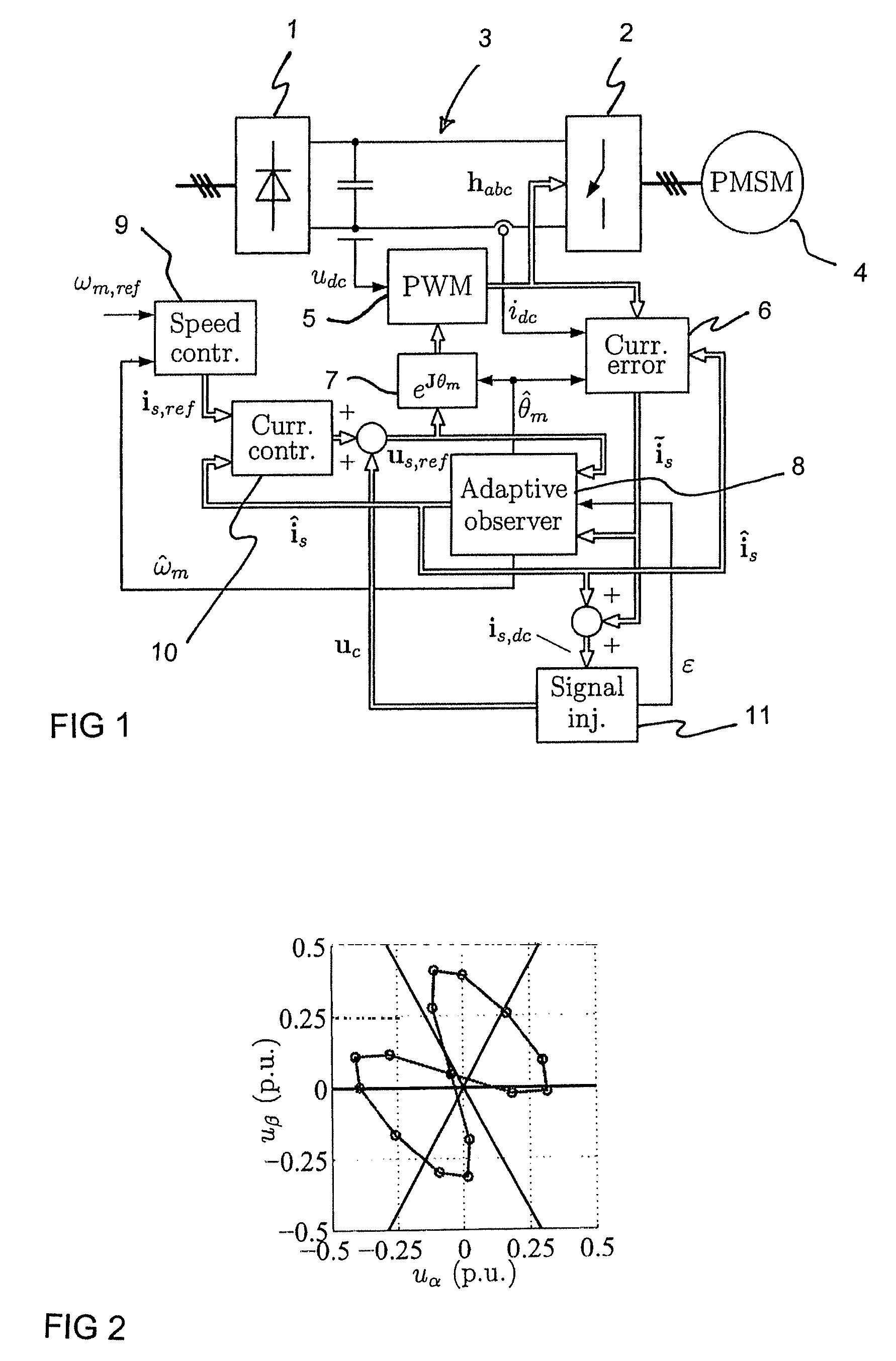
[0025]A block diagram of a control system comprising cascaded speed and current control loops is shown in FIG. 1. A speed controller 9 receives an angular speed reference ωm,ref and an estimated angular speed {circumflex over (ω)}m as feedback. A current controller 10 receives a stator current reference is,ref from the speed controller 9 and a stator current estimate îs from an observer as feedback.

[0026]FIG. 1 also shows a basic structure of a frequency converter which consists of a rectifying bridge 1, a DC-intermediate circuit, i.e. a DC-link 3, and an inverter 2 feeding a PMSM 4. The only measured quantities needed for the control of PMSM are DC-link voltage udc and DC-link current idc at the input of the inverter 2. {circumflex over (ω)}m and {circumflex over (θ)}m are the estimates of the rotor electrical angular speed and position, respectively. A current error ĩs is calculated in block 6 using the estimated current îs, the DC-link current idc, and the referen...


PUM


Abstract

A method for sensorless estimation of rotor speed and position of a permanent magnet synchronous machine, when the permanent magnet synchronous machine is fed with a frequency converter, the method comprising the steps of forming a stator voltage reference for the permanent magnet synchronous machine, injecting a high frequency signal (uc) into the stator voltage reference, measuring a DC-link current (idc) of the frequency converter when the permanent magnet synchronous machine (4) is fed with a voltage (us,ref) corresponding to a sum of the stator voltage reference and the injected signal, calculating a stator current estimate (îs), calculating a current error (ĩs) as a difference between the stator current estimate and the measured DC-link current, and estimating a rotor speed ({circumflex over (ω)}m) and position ({circumflex over (θ)}m) of the permanent synchronous machine based on the current error. The injected high frequency signal (uc) comprises a direct axis component and a quadrature axis component, the direct axis component having a first frequency and the quadrature axis component having a second frequency, the first and second frequencies being different.

Description

FIELD OF THE INVENTION[0001]The present invention relates to sensorless control of permanent magnet synchronous machines (PMSM), and more particularly to control of PMSMs with DC-current measurement.BACKGROUND OF THE INVENTION[0002]Vector control of AC motors requires feedback from phase currents of a motor. Usually, these currents are obtained by measuring at least two of the phase currents. The currents have to be measured by devices that are electrically isolated from control electronics. Hall-effect sensors, which are commonly used for this purpose, are expensive components in low-cost frequency converters. In addition, deviations in the gains between current sensors of different phases may cause current ripple and, consequently, torque ripple. A cost-effective alternative to the phase current measurement is to measure the DC-link current of a frequency converter as in [1] T. C. Green and B. W. Williams, “Derivation of motor line-current waveforms from the DC-link current of an ...

Claims


Application Information

Patent Timeline
Patent Type & Authority Patents(United States)
IPC IPC(8): H02P1/46
CPCH02P6/183H02P6/185H02P21/0042H02P21/13H02P21/146H02P2203/11H02P21/26H02P21/18
Inventor PIIPPO, ANTTI
Owner ABB (SCHWEIZ) AG
Why Eureka
Try Eureka