Broad speed range generator

a generator and wide-range technology, applied in the direction of electric generator control, machine/engine, dynamo-electric converter control, etc., can solve the problems of inability to use a series low-loss ferrite core inductor, inability to regulate the power of the induction machine,

Inactive Publication Date: 2010-11-11
FRADELLA RICHARD B
View PDF2 Cites 71 Cited by
  • Summary
  • Abstract
  • Description
  • Claims
  • Application Information

AI Technical Summary

Benefits of technology

[0029]Optimally loaded wind turbines can harvest sustainable mechanical power from highly variable winds. My present invention generator can convert highly variable shaft power to usable electric power having regulated current and voltage. An embodiment for wind power efficiently generates electric power that is proportional to the third power of speed, over a very broad speed range. It would greatly enhance power quality and produce approximately double the prior art generator electric power energy yields from wind, by harvesting electric power during prevalent low wind speeds and continue to harvest electric power over the entire wind speed spectrum.
[0043](4) Signal processing electronics, normally responsive to the rotor magnet and current sensors, and to DC voltage feedback, to control stator current by PWM and thereby efficiently generate regulated DC current and voltage, from wide speed range rotational power, by boost regulation (fly-back inductor and free-wheeling diode pulse current generation and rectification filtered by high-frequency pulse averaging capacitors). This enables useful DC power generation at requisite DC voltage over a very broad speed range.

Problems solved by technology

However, induction machines generate power only when shaft speed exceeds that needed at zero slip speed.
Moreover, their power is unregulated, and they must be disconnected from the grid at very high wind speeds, because their power fluctuations and internal generator heating are excessive.
Moreover, the iron cores of said induction machines have high inductance, so it is not feasible to use a series low-loss ferrite core inductor as described for the present invention.
Induction machine core loss would be very high, with attendant heating problems, if subjected to high-frequency switching pulse-duration-modulation (PWM) to provide poly-phase sinusoidal voltages having low harmonic distortion across the induction machine stator winding terminals.
Coning torque (wherein the rotor angle aligns its iron cores with and holds minimum magnetic reluctance positions), like stiction and friction in gears, may cause wind turbines to stall at low wind speeds.
These shortcomings and too low output voltage at low shaft speeds prevent usable power generation at low wind speeds from this prior art machine.
Adding a boost regulator in series with the rectified and filtered alternator type generator output can facilitate higher voltages at low shaft speeds, needed for loads such as chemical batteries, but the boost regulator incurs tandem losses and machine cogging may stall the wind turbine driving it so no electric power output is produced from this prior art machine at low wind speeds.
However, their varying voltage and frequency can be a major drawback.
Moreover, very low frequency ripple at low shaft speed requires large filter capacitors, which cost more and have shorter lifetimes than ceramic or film capacitors.
These properties usually limit synchronous generator applications to high shaft speeds.
Their cogging torque is another drawback.
Therefore, they cannot deliver battery charging current at low shaft speeds, and a battery charger may be required to control charging current and voltage.
Besides shorter lifetimes due to their commutator brush and armature wear, commutator sparking can be troublesome; and, similar to most prior art generators, their DC output voltage is proportional to shaft speed.
Moreover, their varying output voltage precludes many low shaft speed applications, unless their output is connected to loads via boost regulator circuits.
Such external and series electronics reduces overall power efficiency, particularly at low turbine shaft speeds.
Besides these limitations, brush-commutated generators also need periodic commutator maintenance; as their commutators are damaged with use, by wear and sparking.
Gearing needed to increase prior art generator shaft speed, so prevalent in wind power systems, also needs bearings for the gears, is subject to wear, needs periodic maintenance, and incurs power losses.

Method used


Image

  • Broad speed range generator
  • Broad speed range generator
  • Broad speed range generator

Examples


Embodiment Construction

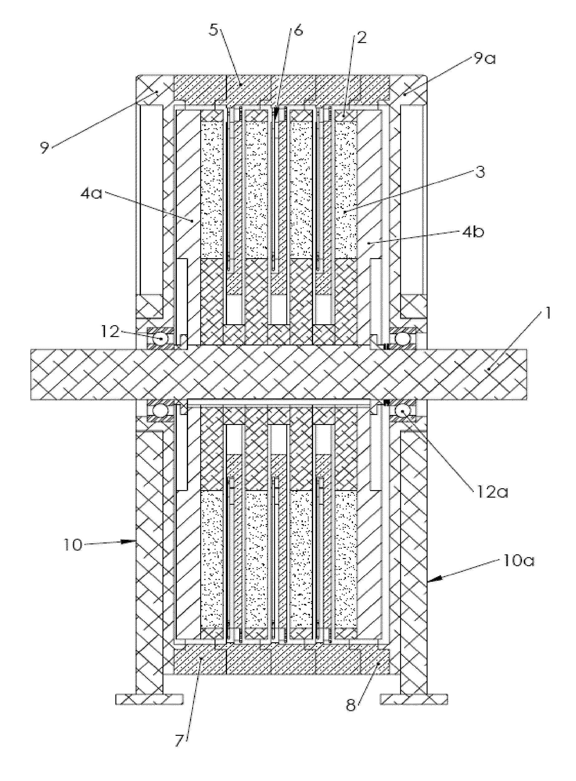
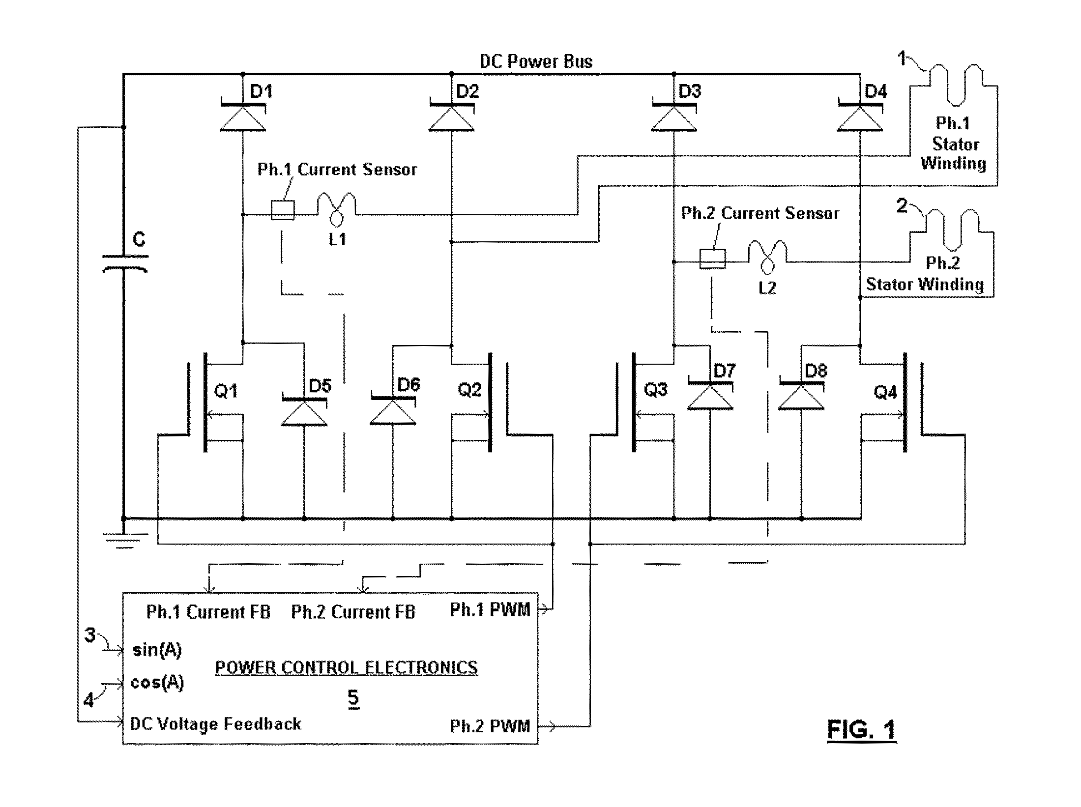
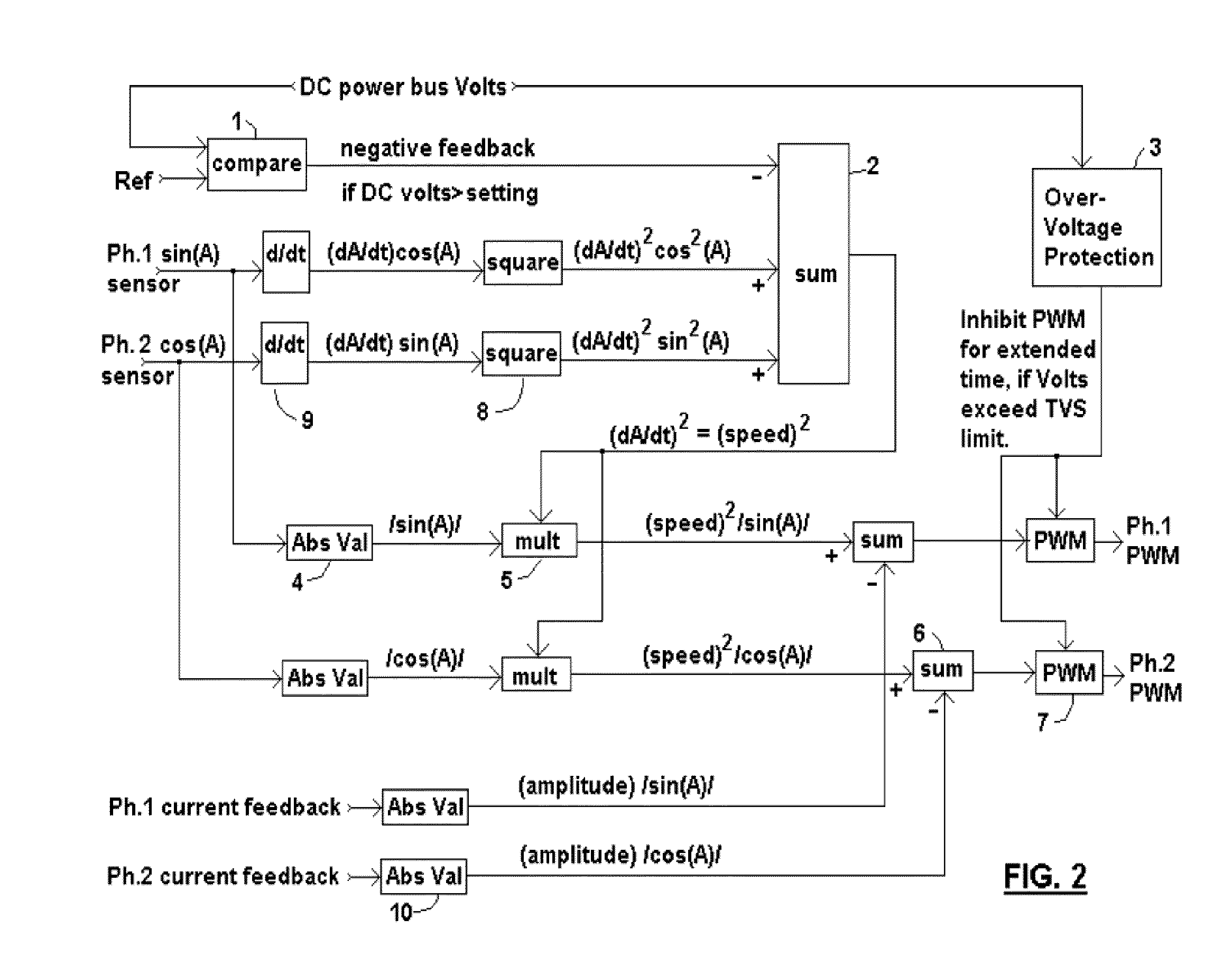
[0063]Main elements and combinations of this new generator are set forth herein and illustrated in FIG. 1. This invention implements a new cooperative combination of elements based upon several engineering disciplines. They include electronics, magnetics, feedback control systems, thermal, magnetic and stress finite-element-analysis, SPICE dynamic circuit and system simulation, rotational dynamics, aerodynamics, hydrodynamics, and materials science, Each discipline has standard terminology and illustration methods, to convey its structures and system combinations in the most concise and understandable way to persons versed in those disciplines. The descriptions and illustrations herein are intended to convey the most essential features of the present invention accurately, clearly, and concisely. Features set forth in prior art, with new improvements facilitated by the present invention, are herein briefly described, to explain differences and to provide clear comparisons. While dime...


PUM


Abstract

A brushless generator with permanent-magnet multi-pole rotor disks and coreless stator winding disks includes integral electronics to efficiently generate regulated DC current and voltage from shaft input power over a broad speed range. Its power rating is scalable, and it incurs no cogging torque, or friction from gearing. Integral power control electronics includes high-frequency pulse-width-modulated boost regulation, which provides regulated current at requisite voltage over its broad speed range. A main embodiment to produce DC power at widely variable speeds includes signal processing so output power varies according to the third power of speed. A version for use with vertical-axis wind turbines has a relatively large diameter to facilitate a large number of poles. Combined boost-regulation, zero cogging torque, and no gearing, enable a wide speed range, for better power quality and higher wind energy yields. An alternate embodiment is intended to produce DC power from a variety of shaft drive sources, with selectable shaft torque.

Description

BACKGROUND OF THE INVENTION[0001]1. Field of the Invention[0002]This invention pertains generally to rotary dynamoelectric machines, and more particularly to dynamoelectric machines having novel rotor and stator structures, to generators having permanent-magnet axial-field rotor and stator disks, and further to cooperative integrated electronics for wide range power control and efficient electric power interface with loads.[0003]Applicant sets forth a brushless self-synchronous generator with permanent-magnet rotor disks and stator winding disks, including integral electronics, to efficiently generate DC (direct-current) electric power, at current and voltage regulated by the electronics, from broadly variable speed rotary mechanical drive. Its various embodiments are intended to generate useful electric power efficiently, especially at low speed and torque, from a wide variety of variable speed and torque drive sources. Moreover, it is intended to substantially improve and expand s...

Claims


Application Information

Patent Timeline
Patent Type & Authority Applications(United States)
IPC IPC(8): F03D3/00H02K11/04H02P9/48F03D1/00H02K9/22H02K7/102H02K16/02F03B13/00F03G5/06
CPCH02K1/2793H02K3/47H02K11/0021H02K21/24H02P2101/30H02K7/1838H02P2101/10H02P2101/15H02P9/48H02K11/215H02M1/0085Y02E10/76H02K1/2798
Inventor FRADELLA, RICHARD B.
Owner FRADELLA RICHARD B
Why Eureka
Try Eureka