Rotor and bearing system for a turbomachine

a technology of rotor bearing and turbine, which is applied in the direction of positive displacement liquid engine, piston pump, liquid fuel engine, etc., can solve the problems of affecting the longevity of the journal and thrust bearing mounted adjacent to the turbine, affecting the longevity of the turbine, and the failure of the compressor to ensure the proper gas transfer between the bearing and the turbine, etc., to achieve the effect of increasing stress, increasing load, and increasing temperatur

Active Publication Date: 2006-09-26
CAPSTONE GREEN ENERGY CORP
View PDF23 Cites 64 Cited by
  • Summary
  • Abstract
  • Description
  • Claims
  • Application Information

AI Technical Summary

Benefits of technology

[0016]The inventive bearing system includes a single bearing positioned between the turbine and the impeller. Due to the operation and the logistics of the individual components of the turbo generator, the area between the turbine and the impeller is the area of the shaft that experiences the higher temperature, larger load, increased stressed, and larger radial forces as compare to the other portions of the shaft. As such, it is contemporary wisdom to position multiple bearings within this area of increased temperature, pressure, and stress. The current invention, however, provides a unique break from this conventional wisdom. Namely, the current invention moves all but a single bearing away from this area of increased temperature, stress, and pressure and, in doing so, reduces the overall temperature and wear on the bearings used in the energy conversion machine.
[0030]In yet still another object of the present invention is to provide increased convective cooling for the radial bearing positioned between a compressor and a turbine in a turbomachine.

Problems solved by technology

This is due to the controllable level of heat generated by the smaller overall design of these conventional systems.
However, even in these smaller systems, the tremendous heat generated in the combustion chamber impacts the longevity of the journal and thrust bearings mounted adjacent the turbine.
As such, those journal and thrust bearings can be the first components to fail in these machines because of their exposure to these heat levels.
Also, the configuration of the bearings and rotors in the prior art machines substantially block gas flow from the compressor to the bearings and on to the turbine.
As such, without additional gas passages, or channels designed into the prior art machines, proper gas transfer from the compressor to the bearings and the turbine is not accomplished.
These facts combined with the location of the thrust bearing and journal bearing near the combustion areas in the prior art turbomachines results in high operating temperatures for those prior art bearings.
As such, these prior art bearings must be made of more expensive materials that tolerate high temperatures.
Even then, these bearings in the prior art systems have a tendency to fail, break down, and malfunction.
In larger machines, for example in a 200 kilowatt machine, the inventors have found that the extreme heat generated in the combustion chamber of the machine will exacerbate problems associated with the thrust bearing directly adjacent the hot section of the machine.

Method used


Image

  • Rotor and bearing system for a turbomachine
  • Rotor and bearing system for a turbomachine
  • Rotor and bearing system for a turbomachine

Examples


Embodiment Construction

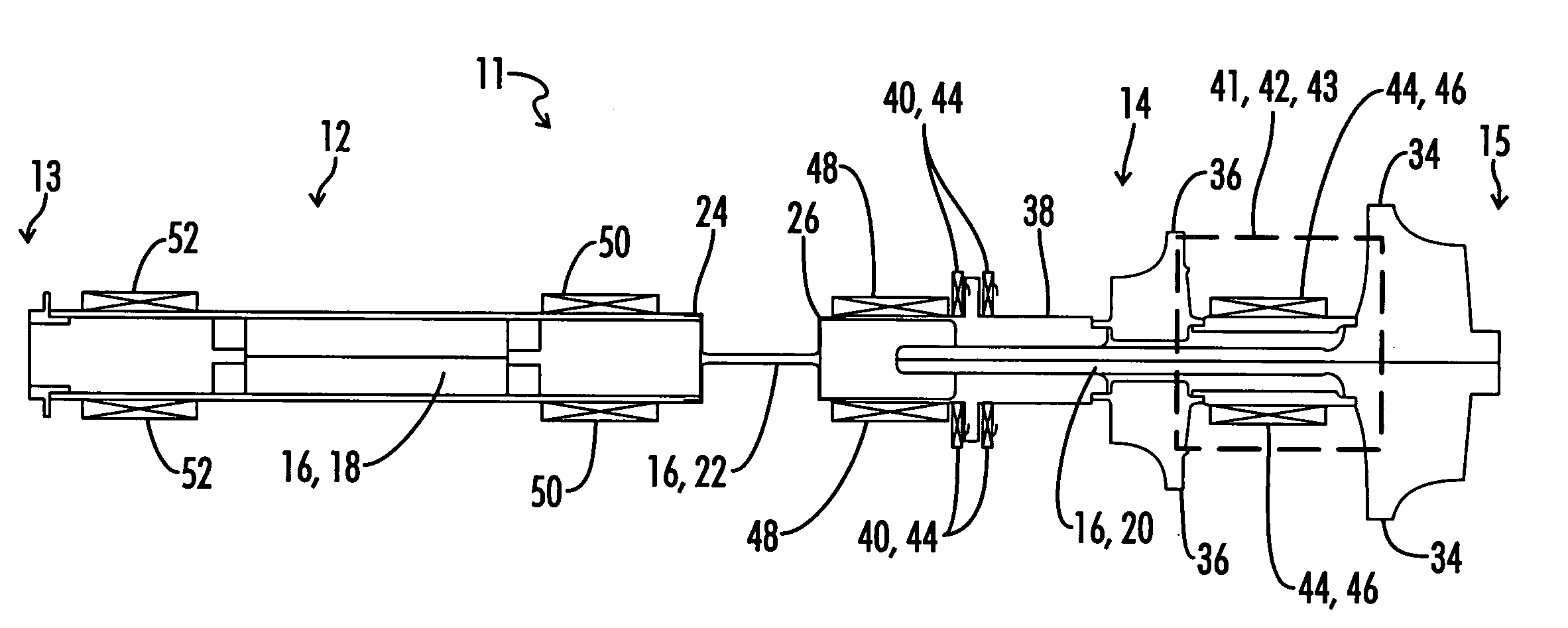
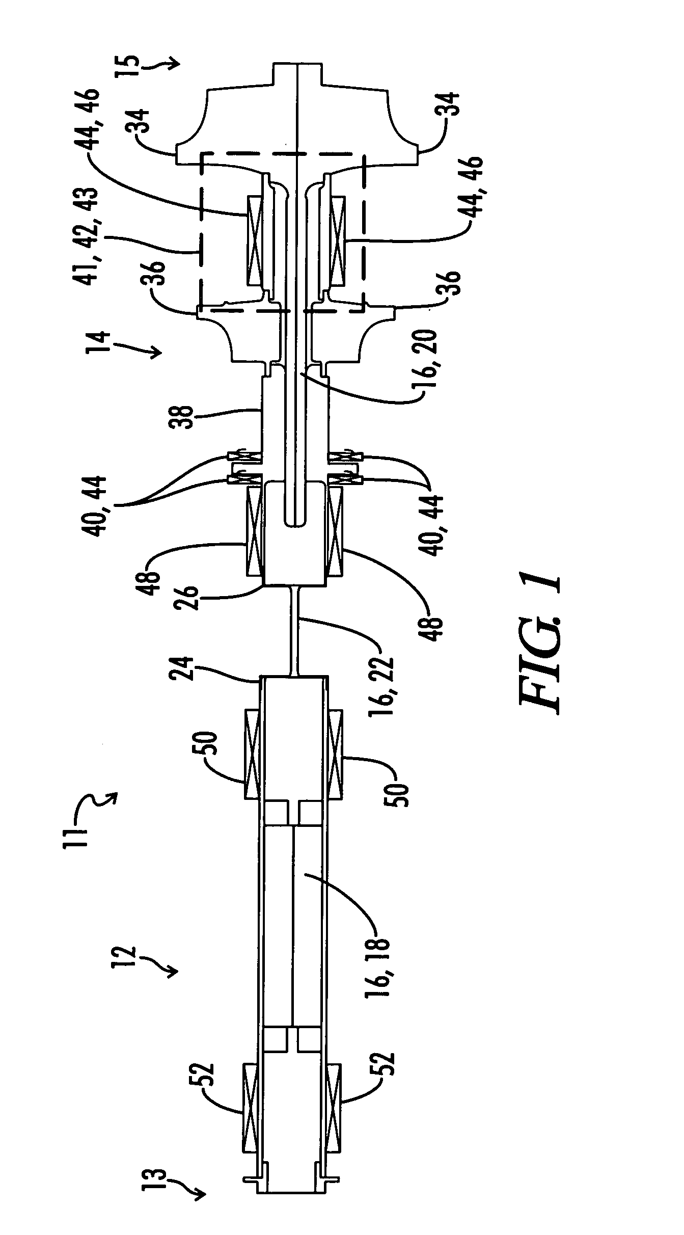
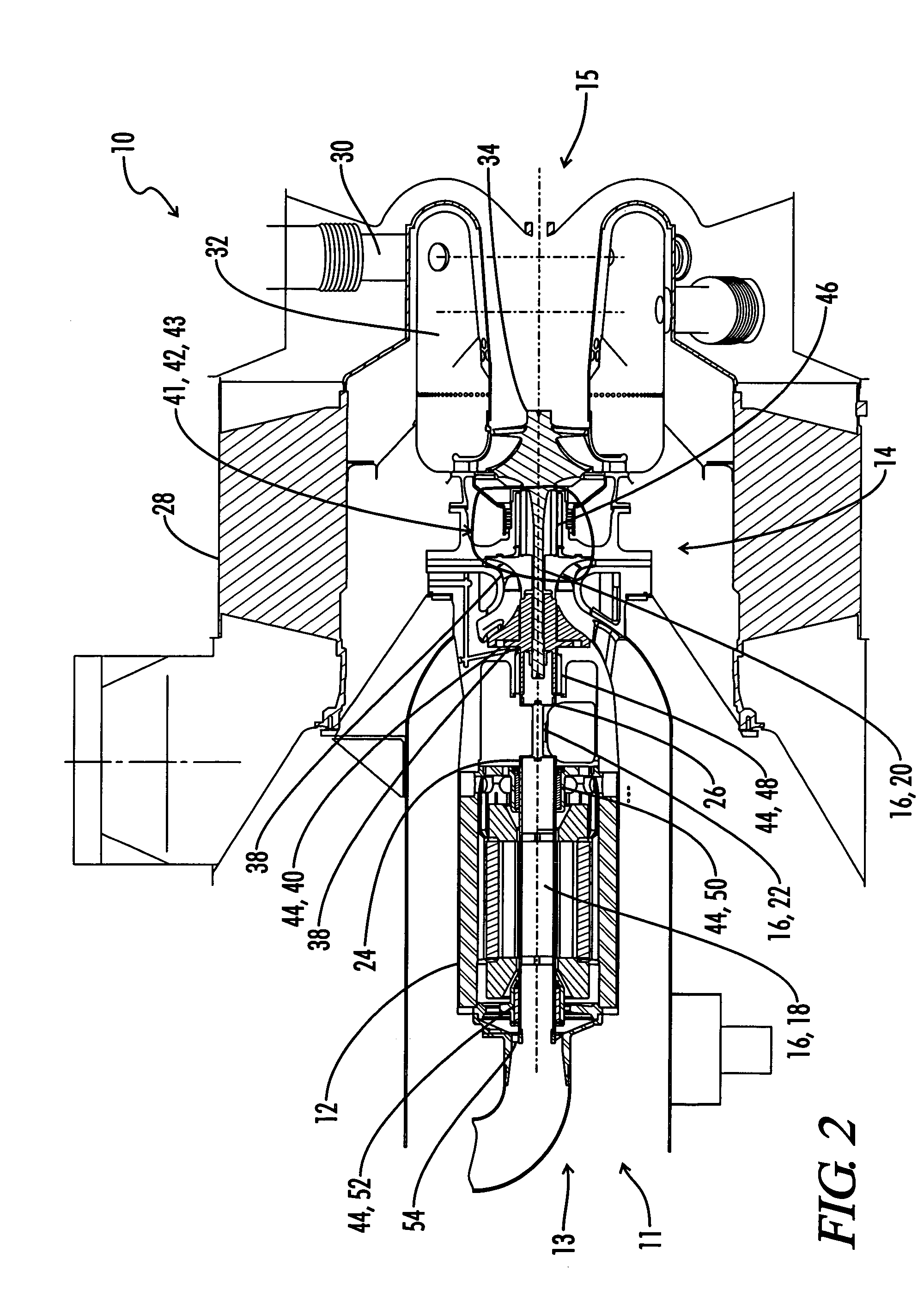
[0037]Referring now generally to FIGS. 1 through 5. An energy conversion machine is shown and generally designated by the numeral 10. The energy conversion machine 10 can also be described as a turbomachine 10. The turbomachine 10 includes a magnetic assembly 12 and a powerhead assembly 14. The magnetic assembly 12 can also be described as the generator 12 or motor 12. Preferably the magnetic assembly 12 uses the kinetic energy of the rotating shaft 16, and more specifically the magnetic shaft 18, to produce electricity.

[0038]The turbomachine 10 includes a heat exchanger 28 which can also be described as a recouperator 28, or recuperator 28, used to increase energy conversion efficiency. The fuel injector 30 is used to supply fuel to the combustion chamber 32 which then uses the ignited fuel to supply the energy force used to propel the powerhead assembly 14.

[0039]Also included is a shaft 16 spanning the magnetic assembly 12 and the powerhead assembly 14. The shaft 16 includes a mag...


PUM


Abstract

A rotor and bearing system for a turbomachine. The turbomachine includes a drive shaft, an impeller positioned on the drive shaft, and a turbine positioned on the drive shaft proximate to the impeller. The bearing system comprises one gas journal bearing supporting the drive shaft between the impeller and the turbine. The area between the impeller and the turbine is an area of increased heat along the drive shaft in comparison to other locations along the drive shaft. The section of the drive shaft positioned between impeller and the turbine is also a section of the drive shaft that experiences increased stressed and load in the turbomachine. The inventive bearing machine system positions only one radial bearing in this area of increased stress and load.

Description

CROSS-REFERENCES TO RELATED APPLICATIONS[0001]This application is a claims benefit of co-pending U.S. patent application Ser. No. 60 / 515,078 filed Oct. 28, 2003, entitled “Rotor and Bearing System for a Turbomachine”, and co-pending U.S. Provisional Patent Application Ser. No. 60 / 559,378 filed Apr. 2, 2004, entitled “Rotor and Bearing System for a Turbomachine”, both of which are hereby incorporated by reference in their entirety.STATEMENT REGARDING FEDERALLY SPONSORED RESEARCH OR DEVELOPMENT[0002]This invention was made in conjunction with the United States Department of Energy's Advanced Microturbine System Project under contract number DE-FC 02-00CH11058. The United States government may have certain rights in this invention.BACKGROUND OF THE INVENTION[0003]The present invention relates to a unique and novel rotor and bearing system for an energy conversion machine, and more specifically to the placement of rotors and bearings within a turbomachine.[0004]A turbomachine is an ener...

Claims


Application Information

Patent Timeline
Patent Type & Authority Patents(United States)
IPC IPC(8): F01D3/04F01D15/10F01D25/16F01D25/22
CPCF01D25/22F01D25/16
Inventor LUBELL, DANIELWEISSERT, DENNIS
Owner CAPSTONE GREEN ENERGY CORP
Why Eureka
Try Eureka