Customizable modular handle structure for sports equipment
- Summary
- Abstract
- Description
- Claims
- Application Information
AI Technical Summary
Benefits of technology
Problems solved by technology
Method used
Image
Examples
Embodiment Construction
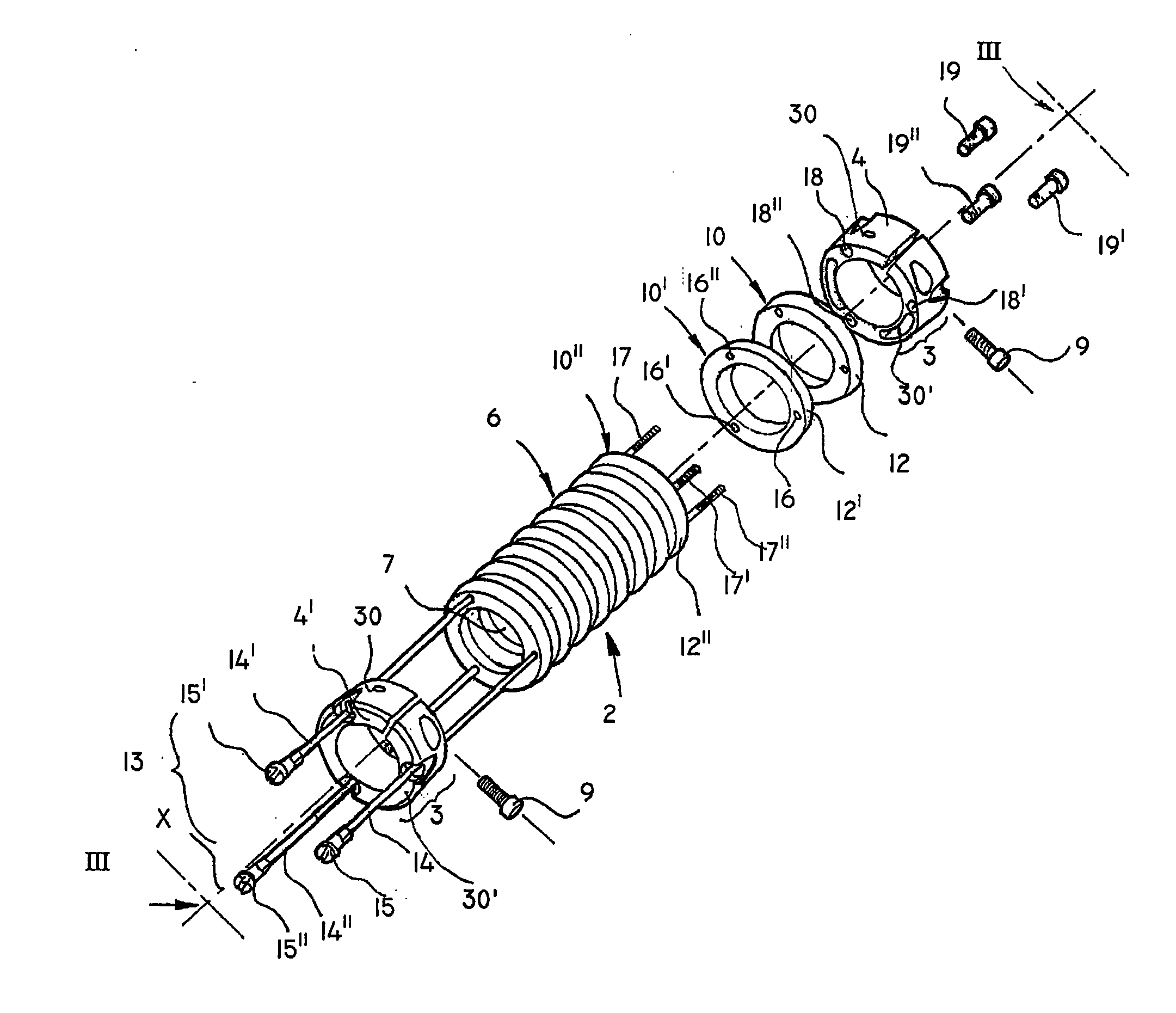
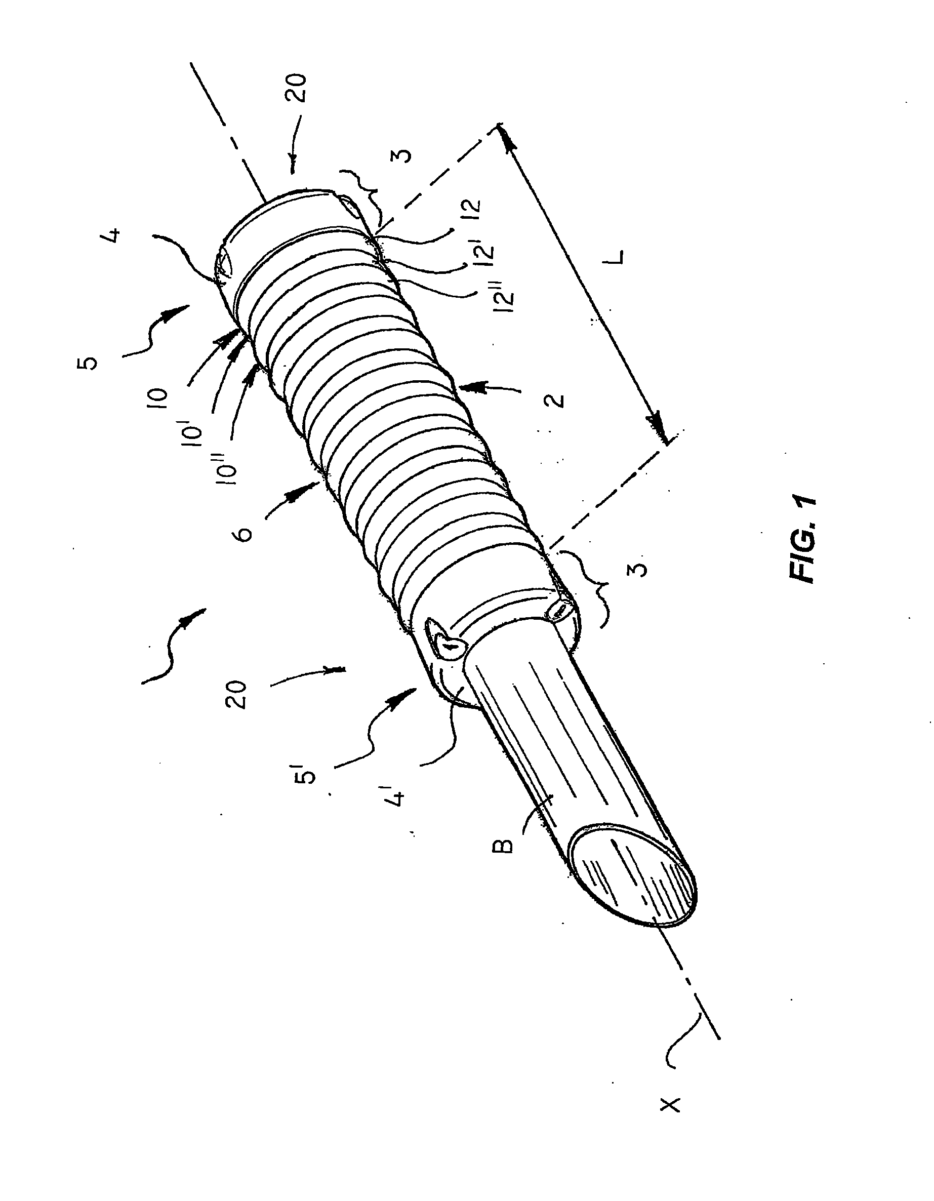
[0022]Referring to the above figures, the handle structure of the invention, generally designated with numeral 1, is designed to be mounted to grip bars B of sports equipment, as shown in FIG. 1.
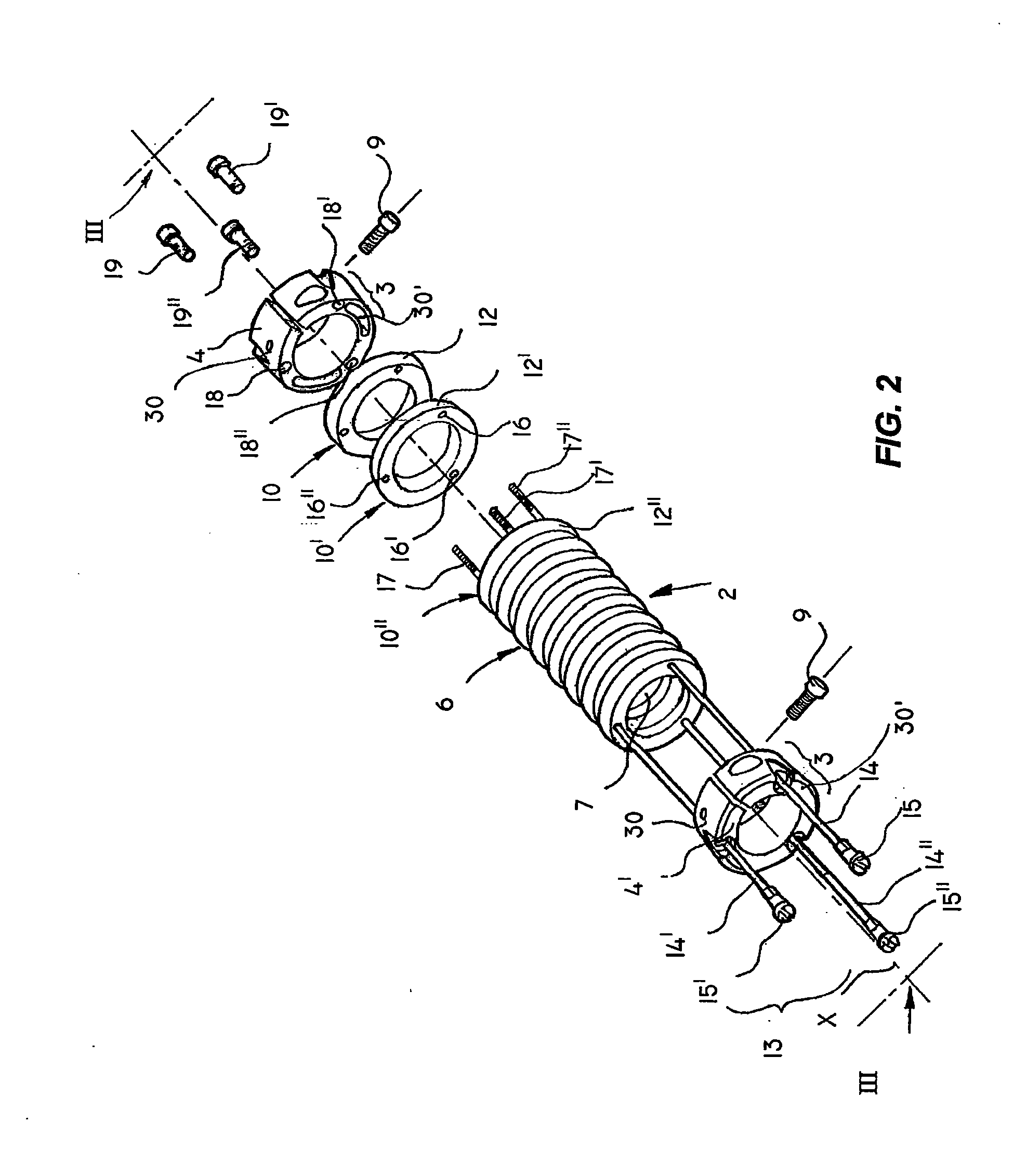
[0023]Basically, the structure 1 has a main tubular body 2 which defines a longitudinal axis X, and first means for axially locking it to the bar (B), generally designated by numerals 3, 3′, comprising a pair of clamping rings 4, 4′ at the longitudinal ends 5, 5′ of the tubular body 2.
[0024]The latter has an outer surface susceptible of being grasped by a user and an inner surface 7 designed to be operably, i.e. during the normal designed use of the handle structure 1, attached to the bar B.
[0025]As particularly shown in FIG. 2, the clamping rings 4, 4′ are of the open type with a substantially radial aperture 8, 8′ closed by a substantially tangential screw 9, 9′.
[0026]The tubular body is formed of a plurality of modular annular elements 10, 10′, 10″, designed for mutual coaxial connection ...
PUM
 Abstract
Description
Claims
Application Information
 - R&D
- Intellectual Property
- Life Sciences
- Materials
- Tech Scout
- Unparalleled Data Quality
- Higher Quality Content
- 60% Fewer Hallucinations
Browse by: Latest US Patents, China's latest patents, Technical Efficacy Thesaurus, Application Domain, Technology Topic, Popular Technical Reports.
© 2025 PatSnap. All rights reserved.Legal|Privacy policy|Modern Slavery Act Transparency Statement|Sitemap|About US| Contact US: help@patsnap.com


