Image display panel, image display apparatus driving method, image display apparatus assembly, and driving method of the same
- Summary
- Abstract
- Description
- Claims
- Application Information
AI Technical Summary
Benefits of technology
Problems solved by technology
Method used
Image
Examples
first embodiment
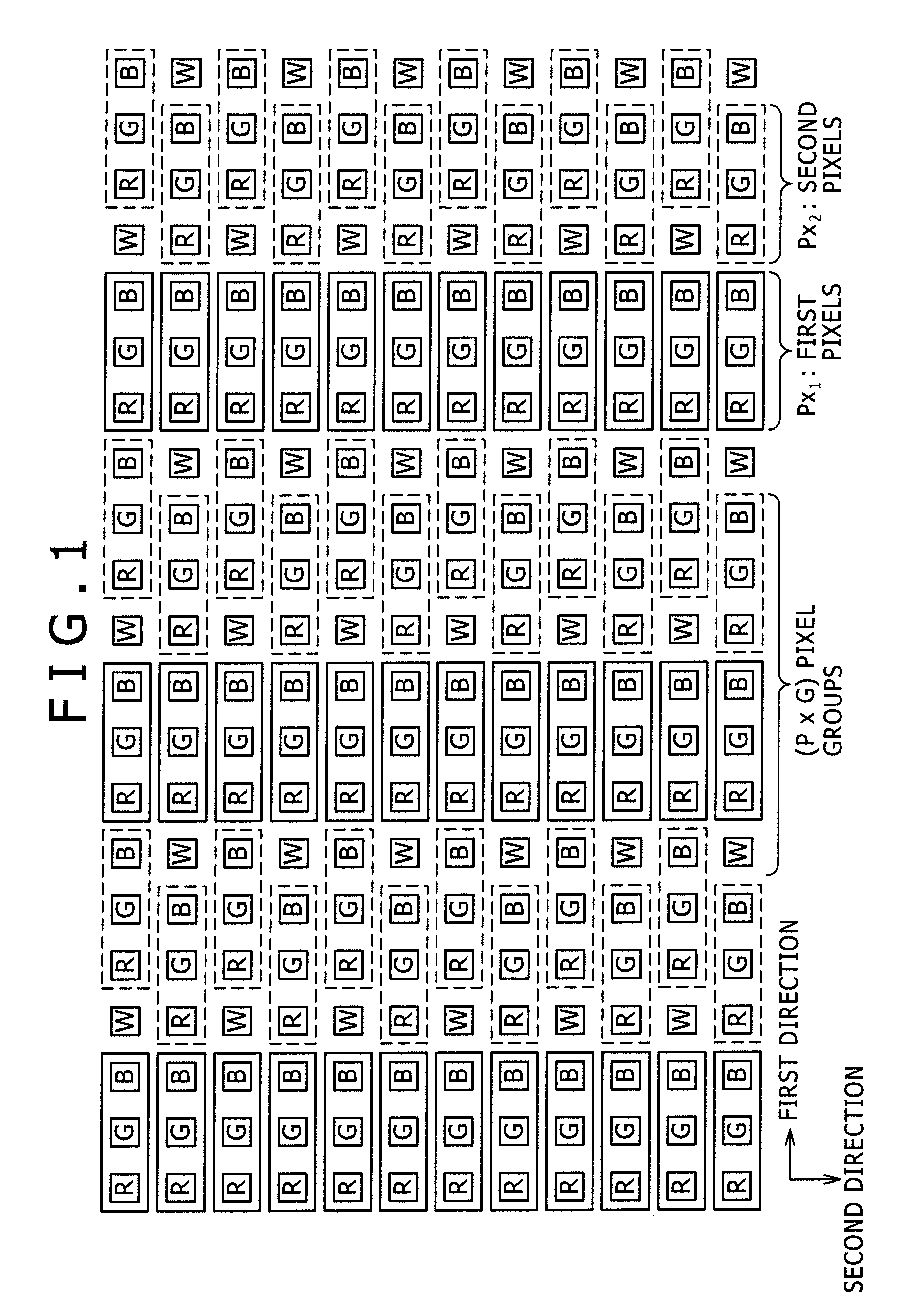
[0249]A first embodiment implements an image display panel provided by the present invention, a method for driving an image display apparatus employing the image display panel, an image display apparatus assembly employing the image display apparatus and a method for driving an image display apparatus assembly. To put it more concretely, the first embodiment implements a configuration according to the (1-A)th mode, a configuration according the (1-A-1)th mode and the first configuration mentioned previously.
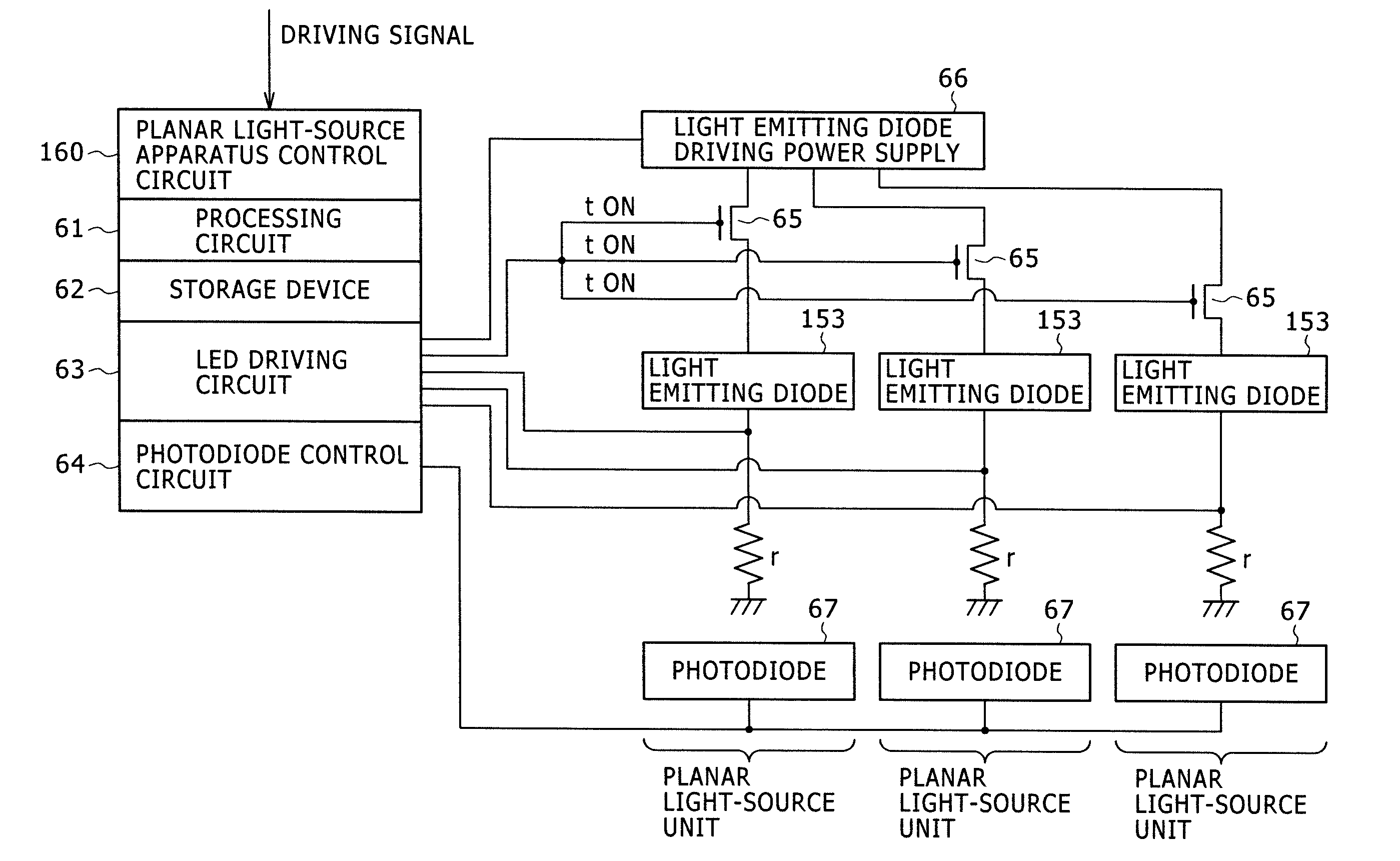
[0250]As shown in a conceptual diagram of FIG. 4, the image display apparatus 10 according to the first embodiment employs an image display panel 30 and a signal processing section 20. The image display apparatus assembly according to the first embodiment employs the image display apparatus 10 and a planar light-source apparatus 50 for radiating illumination light to the rear face of the image display apparatus 10. To put it more concretely, the planar light-source apparatus 50 i...
second embodiment
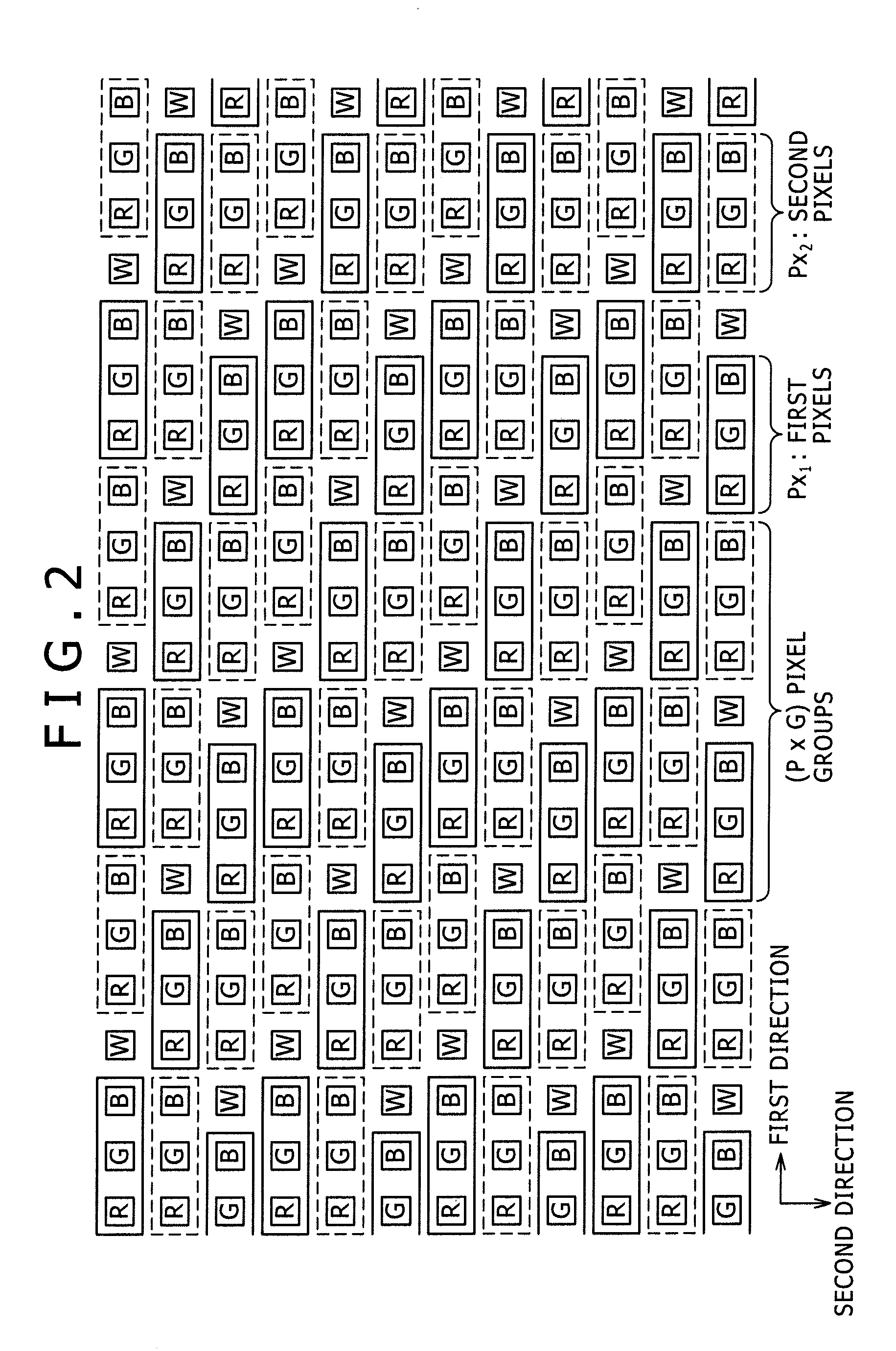
[0331]A second embodiment is obtained as a modified version of the first embodiment. To be more specific, the second embodiment is obtained as a modified version of the array consisting of the first pixel Px1, the second pixel Px2 and the fourth sub-pixel W. That is to say, in the case of the second embodiment, as shown in a model diagram of FIG. 2 in which the row direction is taken as the first direction whereas the column direction is taken as the second direction, it is possible to provide a configuration in which the first pixel Px1 on the q′th column is placed at a location adjacent to the location of the second pixel Px2 on the (q′+1)th column whereas the fourth sub-pixel W on the q′th column is placed at a location not adjacent to the location of the fourth sub-pixel W on the (q′+1)th column where notation q′ denotes an integer satisfying the relations 1≦q′≦(Q−1).
[0332]Except for the difference described above as a difference of the array consisting of the first pixel Px1, t...
third embodiment
[0333]A third embodiment is also obtained as a modified version of the first embodiment. To be more specific, the third embodiment is obtained as a modified version of the array consisting of the first pixel Px1, the second pixel Px2 and the fourth sub-pixel W. That is to say, in the case of the third embodiment, as shown in a model diagram of FIG. 3 in which the row direction is taken as the first direction whereas the column direction is taken as the second direction, it is possible to provide a configuration in which the first pixel Px1 on the q′th column is placed at a location adjacent to the location of the first pixel Px1 on the (q′+1)th column whereas the fourth sub-pixel W on the q′th column is placed at a location adjacent to the location of the fourth sub-pixel W on the (q′+1)th column where notation q′ denotes an integer satisfying the relations 1≦q′≦(Q−1). In typical examples shown in FIGS. 3 and 5, the first sub-pixel, the second sub-pixel, the third sub-pixel and the ...
PUM
 Abstract
Description
Claims
Application Information
 - R&D
- Intellectual Property
- Life Sciences
- Materials
- Tech Scout
- Unparalleled Data Quality
- Higher Quality Content
- 60% Fewer Hallucinations
Browse by: Latest US Patents, China's latest patents, Technical Efficacy Thesaurus, Application Domain, Technology Topic, Popular Technical Reports.
© 2025 PatSnap. All rights reserved.Legal|Privacy policy|Modern Slavery Act Transparency Statement|Sitemap|About US| Contact US: help@patsnap.com


