Blade insert

a technology of inserts and blades, applied in the direction of wind turbines, waterborne vessels, machines/engines, etc., can solve the problems of unacceptable increase of large transfer of traction and/or compression load produced in blade laminations as a result of the action of the wind turbine, etc., to achieve the effect of increasing load in wind turbines

Active Publication Date: 2009-12-31
GAMESA INNOVATION & TECH SA
View PDF5 Cites 37 Cited by
  • Summary
  • Abstract
  • Description
  • Claims
  • Application Information

AI Technical Summary

Problems solved by technology

However, the transfer of traction and / or compression loads produced in the blade's laminations as a consequence of the loads caused in the blade by the action of the wind are very big.
This problem could be solved reinforcing the module walls with more fibre and large inserts, but this excess weight in the blades would unacceptably increase loads in the wind turbine.

Method used


Image

  • Blade insert
  • Blade insert
  • Blade insert

Examples


first embodiment

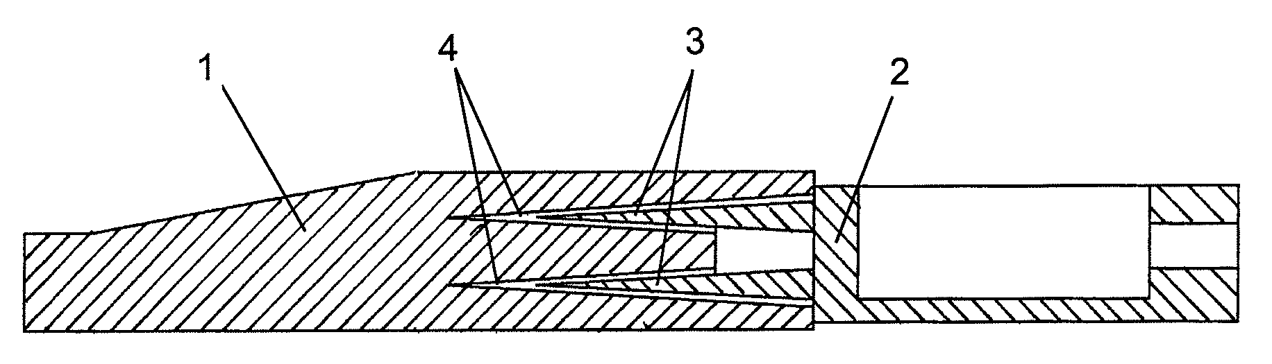
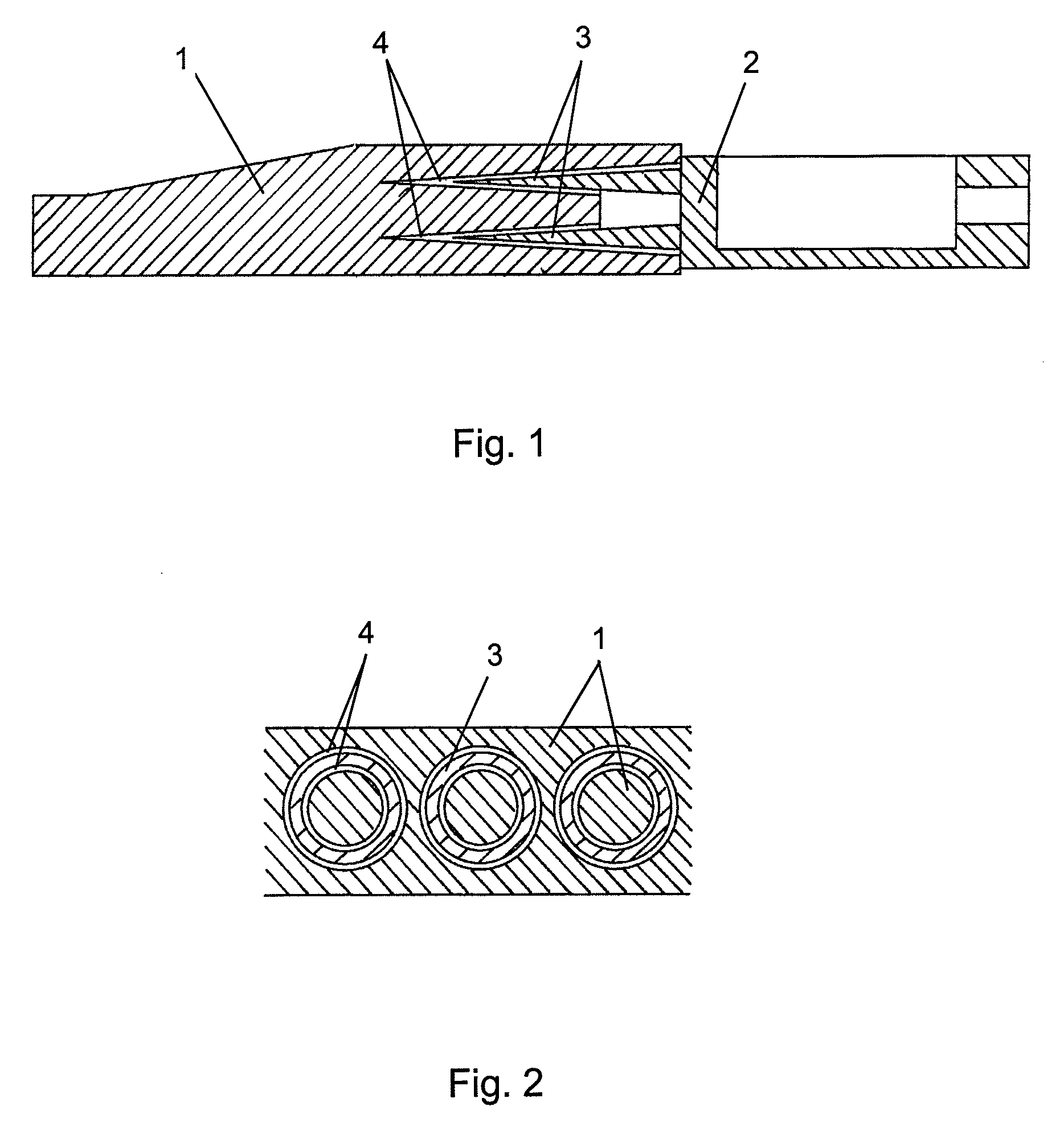
[0014]FIG. 1 shows a section of the insert joint and the blade wall lamination according to a

[0015]FIG. 2 constitutes a transversal section of the joint between the insert and lamination corresponding to the previous figure.

second embodiment

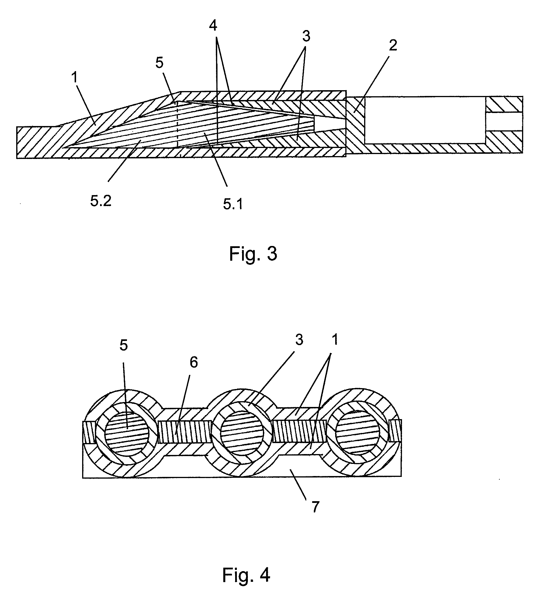
[0016]FIG. 3 shows a section of the insert joint and the blade wall lamination according to a

[0017]FIG. 4 constitutes a transversal section of the joint between the insert and lamination corresponding to the previous figure.

[0018]FIGS. 5 and 6 show a section of the joint indicating the transmission of loads according to the rigidity of the material used in the inner part.

[0019]FIGS. 7 and 8 show two embodiments of the insert head, subject to the present invention, according to its area of implementation in the blade.

[0020]FIG. 9 shows the joint between the two inserts of different structures according to the embodiment in FIG. 7.

[0021]FIG. 10 shows a section of the insert of the joint between the metal fitting, the insert and the bolt according to the embodiment in FIG. 7.

[0022]FIG. 11 shows an embodiment of a tightening tool related to the embodiment of FIG. 7.


PUM

PropertyMeasurementUnit
shapeaaaaaaaaaa
resistanceaaaaaaaaaa
torqueaaaaaaaaaa

Abstract

Blade insert connected in the lamination of a blade determining a double shear joint between insert and lamination. The insert is made up of two defined parts, head (2), designed to screw the insert to another structure (2′), and the body (3) that determines a cylindrical or conical shape with an internal conical cavity. In an embodiment, the insert is designed to be joined to the lamination (1) of the blade with adhesive means (4). In another embodiment, the insert is embedded in the blade lamination with an inner part (5) stuck to the body (3) of the insert.

Description

OBJECT OF THE INVENTION [0001]The invention describes an insert for a wind turbine blade according to the preamble in the first claim.BACKGROUND OF THE INVENTION [0002]Wind turbines blades are typically joined to the wind turbine hub with a mechanical multipoint joints, prestressed with stressed screws. Likewise, the blades divided into several modules can be assembled with mechanical joints between metal parts called inserts. The basic function of these blade root joint elements and the intermediate joint elements is transferring traction and / or compression loads transmitted from the blade laminations.[0003]The nearest state-of-the-art corresponds to patent EP 18789155 where metal inserts axially housed in blade module walls are presented, where this wall is made of a composite lamination with a series of holes. The structural joint between the composite material and the inserts is carried out with chemical means (adhesive) and is defined as a single shear joint, as each side of th...

Claims


Application Information

Patent Timeline
Patent Type & Authority Applications(United States)
IPC IPC(8): F01D5/30B29C45/14
CPCB29C33/42B29C70/72F03D1/0658Y02E10/721F05B2260/301Y02E10/72F05B2250/232B29C70/48B29C70/86B29C70/865B29D99/0025F03D1/0675F05B2240/302Y10T29/49336Y10T29/49337Y10T29/49339Y10T29/49982
Inventor AROCENA DE LA RUA, IONSANZ PASCUAL, ENEKOARROZ COLLADO, SANDRA
Owner GAMESA INNOVATION & TECH SA
Why Eureka
Try Eureka