Image pickup apparatus and auto-focus detection method

Inactive Publication Date: 2010-01-07
CANON KK
View PDF6 Cites 7 Cited by
  • Summary
  • Abstract
  • Description
  • Claims
  • Application Information

AI Technical Summary

Benefits of technology

[0010]The present invention provides an image pickup apparatus and an auto-focus detection method capable of achieving stable focusing on an object, even when focusing is performed based on a recognized object area.

Problems solved by technology

In that case, the focusing cannot be achieved as desired by the photographer, giving a discomfort to the photographer.
With the aforementioned image pickup apparatuses, if hand-shake is caused at high zoom magnification photographing, the resolution of picked-up image is lowered to make it difficult to detect a face to be photographed.
If a face is not detected, focusing cannot be performed by the image pickup apparatuses, posing a problem that it becomes impossible to make focusing on the main object (face) even though the main object is present on the imaging screen.
In a case for example that face detection and non-detection are irregularly repeated depending on imaging state, focusing is made on a face when the face is detected but on the background when no face is detected, posing a problem that stable focusing on the object cannot be achieved.

Method used


Image

  • Image pickup apparatus and auto-focus detection method
  • Image pickup apparatus and auto-focus detection method
  • Image pickup apparatus and auto-focus detection method

Examples


first embodiment

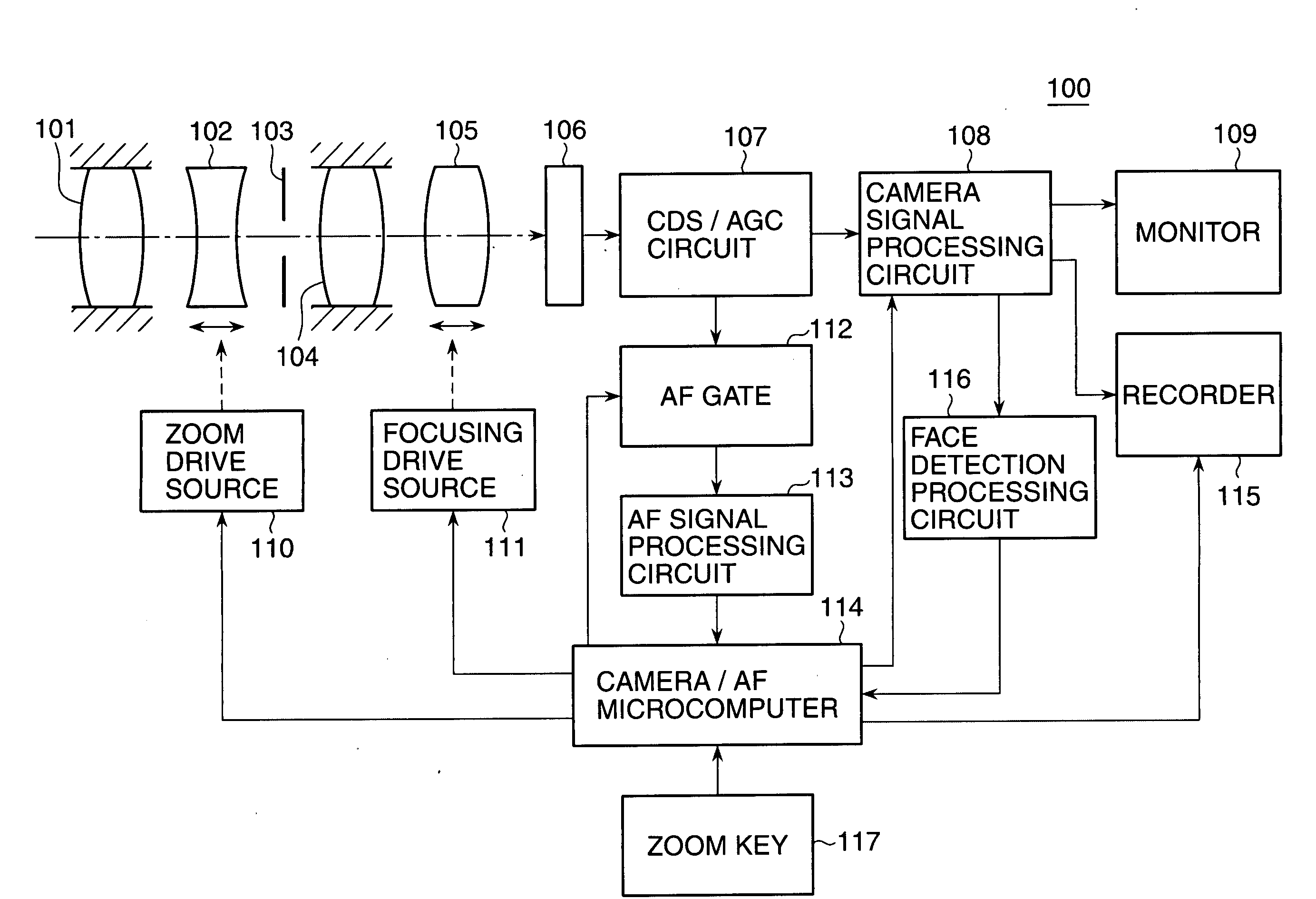
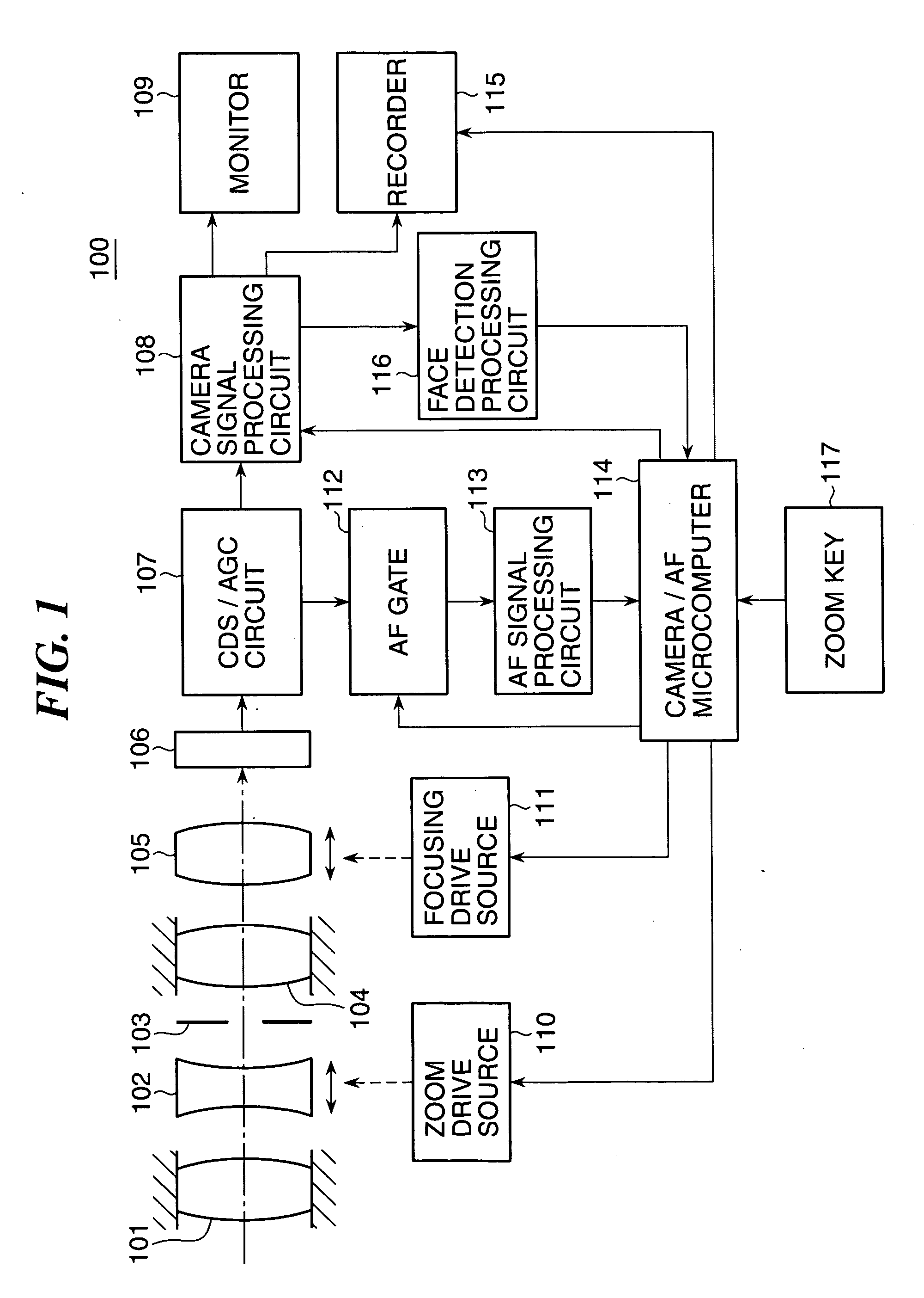
[0036]FIG. 1 schematically shows in block diagram the overall construction of a video camera 100 that functions as an image pickup apparatus according to embodiments of this invention.

[0037]As shown in FIG. 1, the video camera 100 includes a first fixed lens 101, a variable power lens 102 as a zoom lens movable along an optical axis to vary the magnification, an aperture 103, a second fixed lens 104, and a focus lens 105. The focus lens 105 is a so-called focus / compensator lens having both a focusing function and a function of compensating for a focal plane movement due to the alteration of magnification. An image-pickup optical system constituted by the first fixed lens 101, variable power lens 102, aperture 103, second fixed lens 104, and focus lens 105 generates and forms an optical image of an object field on an imaging screen of an image pickup device 106 (image pickup unit).

[0038]The image pickup device 106 is a photoelectric conversion device constituted by a CCD sensor or a ...

second embodiment

[0076]Next, an image pickup apparatus according to a second embodiment is described.

[0077]The overall construction of the image pickup apparatus of this embodiment is the same as or similar to the video camera 100 of the first embodiment, and a description thereof will be omitted.

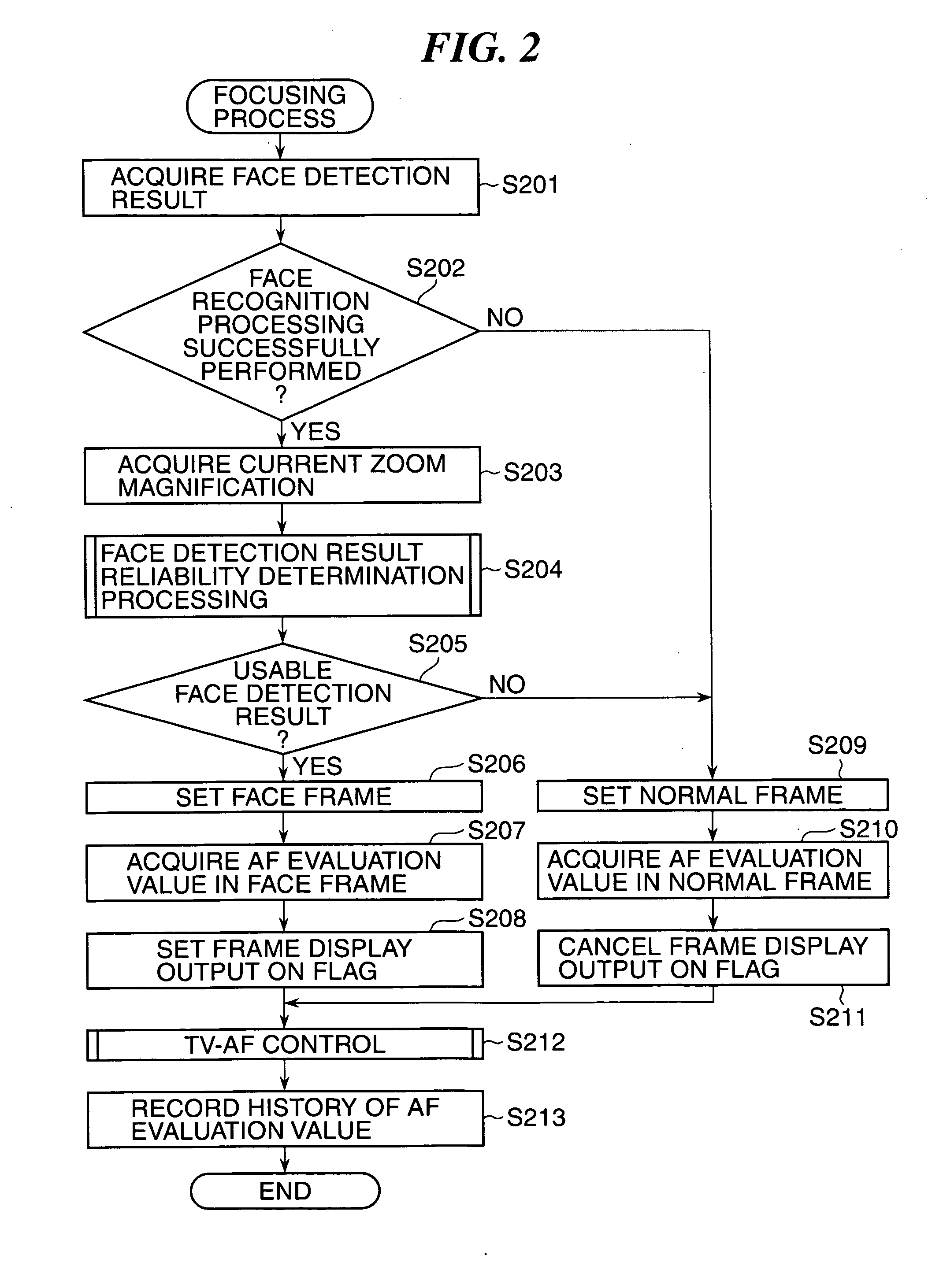
[0078]FIG. 6 shows in flowchart the procedures of a focusing process executed by the image pickup apparatus of the second embodiment, in which AF control and frame display control are carried out according to shutter speed. The focusing process is basically the same as that of the first embodiment (FIG. 2). In FIG. 6, operations common to those shown in FIG. 2 are each denoted by a step number having the same last two digits as that for the corresponding operation in FIG. 2, with a description thereof omitted. In the following, only different operations are described.

[0079]As shown in FIG. 6, if it is determined in step S602 that face recognition processing has been successfully performed, the computer 114 ...

third and fourth embodiments

[0095]Next, third and fourth embodiments are described.

[0096]The overall construction of image pickup apparatuses of the third and fourth embodiments is the same as or similar to the video camera 100 of the first embodiment, and a description thereof will be omitted. A focusing process performed by the image pickup apparatuses of these embodiments is basically the same as that of the first embodiment, and a drawing figure corresponding to FIG. 2 is omitted.

[0097]The following is a description of the third embodiment.

[0098]In the focusing process performed by the image pickup apparatus of this embodiment, a current in-focus degree is acquired instead of a current zoom magnification acquired in step S203 in FIG. 2, and the focusing process is carried out based the acquired in-focus degree.

[0099]The in-focus degree may be one that simply indicates an out-of-focus state when a high-frequency component of a brightness signal of a picked-up image, which represents a focus state of the ima...


PUM


Abstract

An image pickup apparatus capable of focusing on an object with stability based on a recognized object area. A video camera includes an image pickup device for picking up an image formed by an image-pickup optical system including a focus lens, a face detection processing circuit for detecting, based on a video signal output from the image pickup device, an object area on an imaging screen and the likelihood of an object being present in the object area, and a computer for controlling a focus adjustment based on the object area when determining that the likelihood detected by the face detection processing circuit satisfies a predetermined condition, which is varied according to an imaging state.

Description

BACKGROUND OF THE INVENTION[0001]1. Field of the Invention[0002]The present invention relates to an image pickup apparatus and an auto-focus detection method.[0003]2. Description of the Related Art[0004]For auto-focus (AF) control in an image pickup apparatus such as a video camera, a TV-AF system has been mainly used that generates an AF evaluation value signal representing the sharpness, contrast state, etc. of an image signal generated by an image pickup device and adjusts focus lens position so as to attain the maximum of the AF evaluation value signal.[0005]When photographing a person with an image pickup apparatus that performs AF control, focusing is sometimes made not on the person (main object) but on the background depending on a state of contrast between the person and background. In that case, the focusing cannot be achieved as desired by the photographer, giving a discomfort to the photographer.[0006]To obviate this, an image pickup apparatus has been proposed that reco...

Claims


Application Information

Patent Timeline
IPC IPC(8): H04N5/232
CPCH04N5/23219H04N5/23212H04N23/675H04N23/673H04N23/61H04N23/611H04N23/635
Inventor ISHII, KAZUNORI
Owner CANON KK
Why Eureka
Try Eureka