Modulized micro projection device

a micro-projection device and module technology, applied in the field of projection devices, can solve the problems of limiting the selection of light sources and cooling elements, the size of the projection device, and the poor luminance of the micro-projection devi

Inactive Publication Date: 2010-01-07
ARIMA COMP
View PDF3 Cites 1 Cited by
  • Summary
  • Abstract
  • Description
  • Claims
  • Application Information

AI Technical Summary

Benefits of technology

[0006]According to one embodiment of the present invention, a modulized micro projection device includes a case, a lens, an image module and a connection structure. The lens is disposed on one side of the case. The image module is disposed inside the case for projecting an image onto a screen through the lens. The connection structure is disposed on the outer surface of the case and holding a lighting module for providing light to the image module. Therefore, the lighting module is replaceable such that the luminance of the light can be changed through replacing the lighting module.

Problems solved by technology

To reduce the size of the projection device for mobility (so called a micro projection device) becomes a popular issue lately.
However, the reduced size of the micro projection device limits the selection of the light source and the cooling element.
In addition, due to the low power supply of the micro projection device, the micro projection device can only project with poor luminance (about 10 lumens).
Compared with the general projection device, the projecting ability of the micro projection device is not sufficient for general application.

Method used


Image

  • Modulized micro projection device
  • Modulized micro projection device
  • Modulized micro projection device

Examples


Embodiment Construction

[0017]Reference will now be made in detail to the present embodiments of the invention, examples of which are illustrated in the accompanying drawings. Wherever possible, the same reference numbers are used in the drawings and the description to refer to the same or like parts.

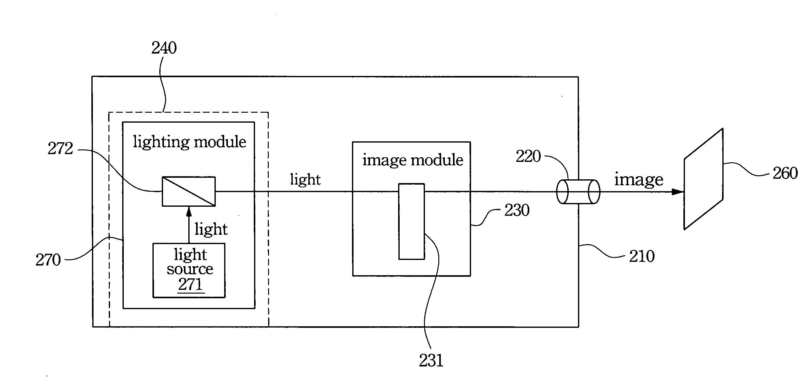
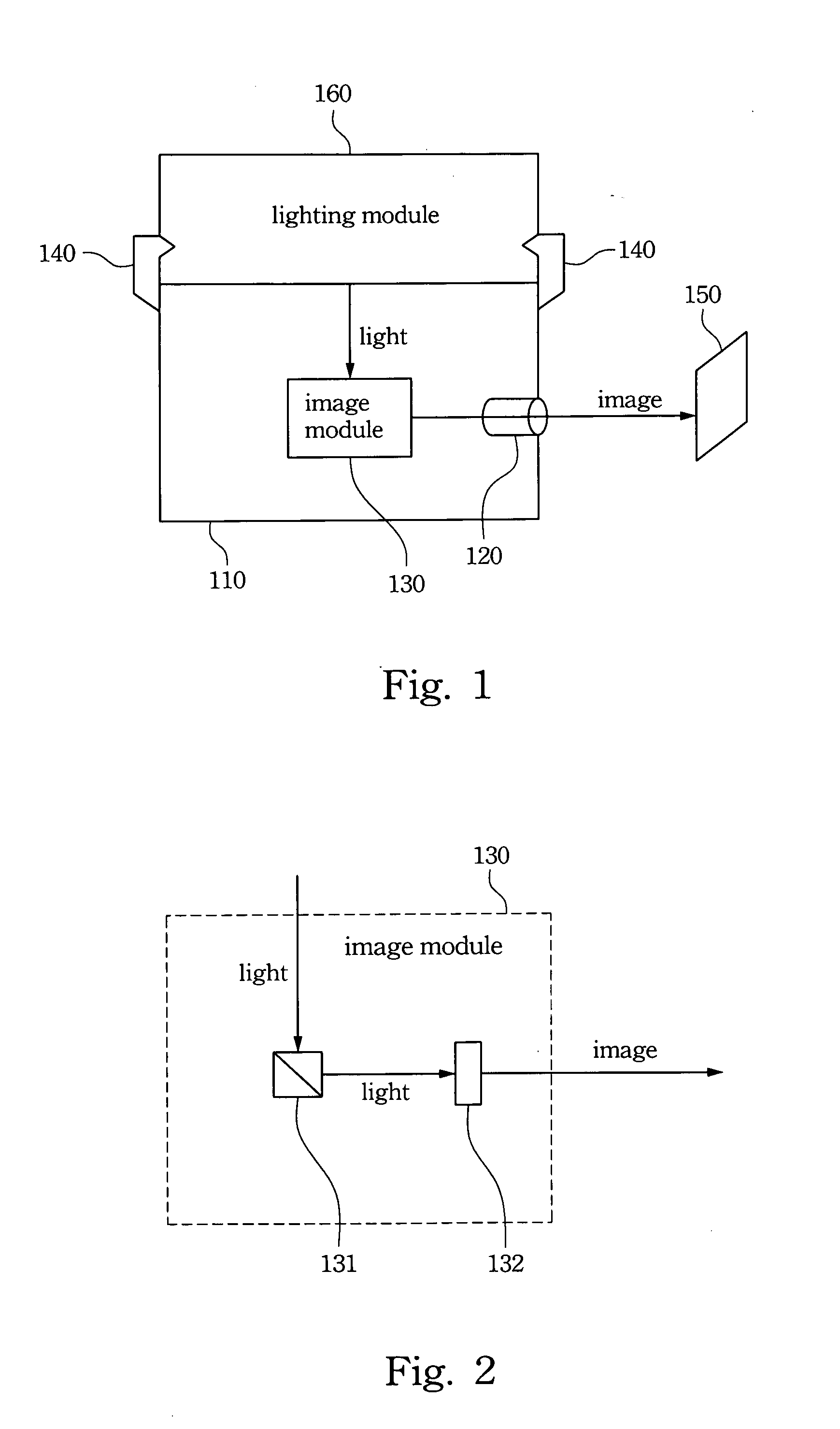
[0018]FIG. 1 illustrates a modulized micro projection device according to one embodiment of this invention. Referring to FIG. 1, the modulized micro projection device comprises a case 110, a lens 120, an image module 130 and a connection structure 140. The lens 120 is disposed on one side of the case 110. The image module 130 is disposed inside the case 110 for projecting an image onto a screen 150 through the lens 120. The connection structure 140 is disposed on the outer surface of the case 110 and holding a lighting module 160 for providing light to the image module 130, wherein the connection structure 140 is a hook set. Therefore, the lighting module 160 is replaceable such that the luminance of the light...


PUM


Abstract

A modulized micro projection device is disclosed. The modulized micro projection device includes a case, a lens, an image module and a connection structure. The lens is disposed on one side of the case. The image module is disposed inside the case for projecting an image onto a screen through the lens. The connection structure is disposed on the outer surface of the case and holding a lighting module for providing light to the image module. Therefore, the lighting module is replaceable such that the luminance of the light can be changed through replacing the lighting module. Another modulized micro projection device is also disclosed.

Description

BACKGROUND[0001]1. Field of Invention[0002]The present invention relates to a projection device. More particularly, the present invention relates to a modulized micro projection device.[0003]2. Description of Related Art[0004]To reduce the size of the projection device for mobility (so called a micro projection device) becomes a popular issue lately. However, the reduced size of the micro projection device limits the selection of the light source and the cooling element. In addition, due to the low power supply of the micro projection device, the micro projection device can only project with poor luminance (about 10 lumens). However, the general projection device can project with thousands of lumens. Compared with the general projection device, the projecting ability of the micro projection device is not sufficient for general application.[0005]Therefore, there is a need for a micro projection device to satisfy the size limitation of the micro projection device and provide sufficien...

Claims


Application Information

Patent Timeline
Patent Type & Authority Applications(United States)
IPC IPC(8): G03B21/20
CPCG03B21/2046G03B21/2093G03B21/20
Inventor LU, H0HUANG, CHIH-SHUNCHIANG, TUNG-CHUN
Owner ARIMA COMP
Why Eureka
Try Eureka