Projector and method for controlling same

a technology of projector and control method, which is applied in the direction of picture reproducers, picture reproducers using projection devices, instruments, etc., can solve the problems of lamp flickering, lamp characteristics degraded, and lamp service life shortened, so as to minimize the change in the luminance of the projected image

Active Publication Date: 2015-02-24
SHARP NEC DISPLAY SOLUTIONS LTD
View PDF30 Cites 1 Cited by
  • Summary
  • Abstract
  • Description
  • Claims
  • Application Information

AI Technical Summary

Benefits of technology

[0019]By controlling the aperture of the optical diaphragm depending on a change in the lighting power of the lamp, a change in the luminance of a projected image is minimized when a lamp refreshing process is performed.

Problems solved by technology

In those instances, the lamp characteristics are degraded, i.e., the service life of the lamp is shortened and lamp flickering occurs.
However, changing the lighting power of the lamp leads to changing the lamp luminance, resulting in a change in the luminance of images projected by the projector.
The disclosed projector, however, is aimed at increasing the contrast of projected images, and serves to regulate the amount of lighting power and the amount of optical diaphragm relative to each other based on an input video signal, and is unable to deal with a change in the luminance of projected images in the lamp refreshing process.

Method used


Image

  • Projector and method for controlling same
  • Projector and method for controlling same
  • Projector and method for controlling same

Examples


first exemplary embodiment

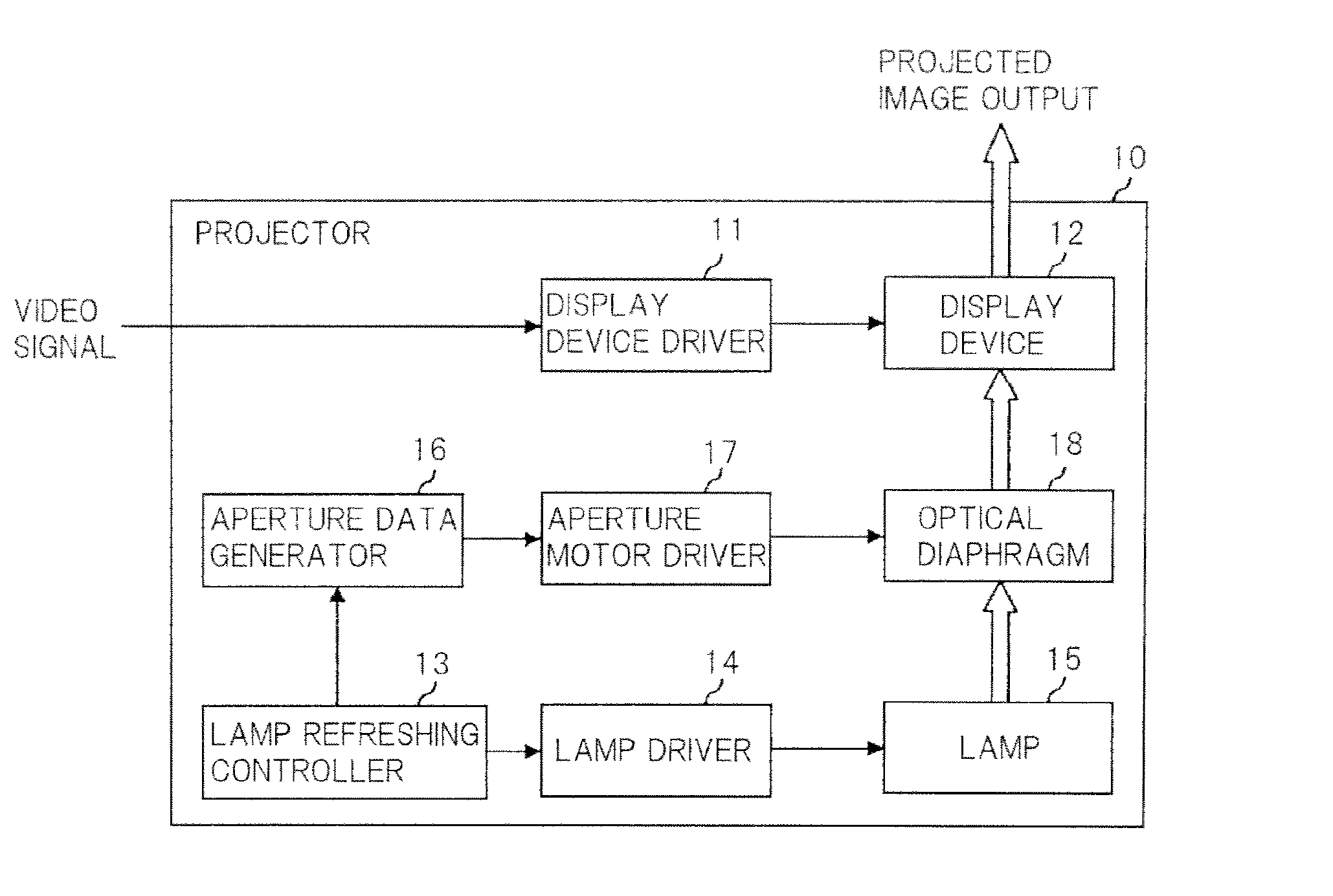
[0029]FIG. 1 is a block diagram showing the configuration of a projector according to a first exemplary embodiment of the invention.

[0030]Projector 10 shown in FIG. 1 includes display device driver 11, display device 12, lamp refreshing controller 13, lamp driver 14, lamp 15, aperture data generator 16, aperture motor driver 17, and optical diaphragm 18.

[0031]In FIG. 1, solid-line arrows represent the inputting and outputting of electric signals, and the blank arrows represent the inputting and outputting of light signals.

[0032]A video signal given from an external source is input to display device driver 11.

[0033]Display device driver 11 drives display device 12 depending on the video signal.

[0034]Display device 12 comprises, for example, a transmissive liquid crystal panel of a general structure, and modulates light emitted from lamp 15.

[0035]If lamp refreshing controller 13 detects when the lighting power of lamp 15 is lower than rated power thereof for a certain period of time o...

second exemplary embodiment

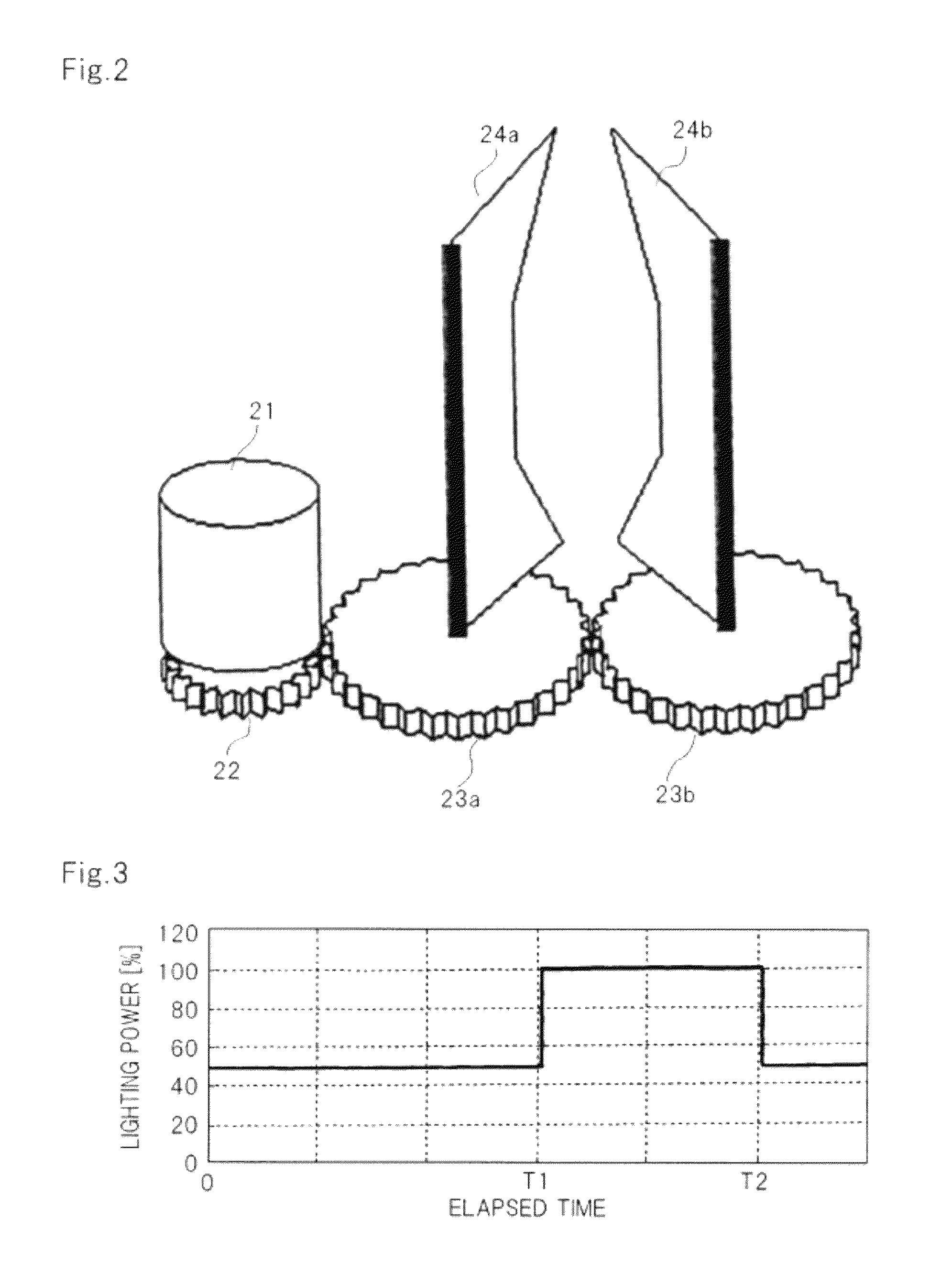
[0069]According to the first exemplary embodiment, lighting power is changed once when the lamp refreshing process is performed.

[0070]Generally, however, the response time of a change in the luminance of a projected image according to positional control by aperture motor 21 is slow compared with the response time of a change in the luminance of light emitted from lamp 15 according to lighting power control. In addition, while the lighting power of lamp 15 and luminance changes are in a proportional relationship, as shown in FIG. 5, the control position of aperture motor 21 and changes in the amount of light passing through optical diaphragm 18 are not in a proportional relationship, as shown in FIG. 4. Therefore, it is difficult to keep the luminance of a projected image constant even if the response times according to lighting power control and positional control by aperture motor 21 are combined with each other.

[0071]According to the present exemplary embodiment, lamp refreshing c...


PUM


Abstract

In order to minimize a change in the luminance of a projected image caused by a lamp refreshing process, projector 10 according to the present invention includes lamp refreshing controller 13 which, upon detecting that the lighting power of lamp 15 is lower than rated power thereof for a given period of time, increases the lighting power of lamp 15 to the rated power and, after elapse of a predetermined period of time, reduces the lighting power to an original level thereof, and aperture data generator 16 which controls the aperture of optical diaphragm 18 depending on a change in the lighting power to keep constant the amount of light passing through optical diaphragm 18.

Description

TECHNICAL FIELD[0001]The present invention relates to a projector and a method of controlling same.BACKGROUND ART[0002]High-pressure discharge lamps (hereinafter referred to as “lamp”) have been used as a general light source for projectors. While a lamp is being lighted, a halogen cycle is caused wherein an electrode substance that is evaporated from electrodes of the lamp by the electric discharge between the electrodes is deposited on the electrodes again by the action of the halogen gas that is sealed in the light emission tube of the lamp. Reduction in the operating life of the lamp and the occurrence of flickering of the lamp can be minimized by appropriately controlling the halogen cycle. The halogen cycle can be controlled based on the lighting power of the lamp, the frequency at which the lamp is lit, and the temperature of the lamp, etc.[0003]There are instances wherein the lamp cannot be lighted with rated power to cause a stable halogen cycle as when the lamp is used wit...

Claims


Application Information

Patent Timeline
Patent Type & Authority Patents(United States)
IPC IPC(8): G03B21/14G03B9/06G03B21/20H04N9/31
CPCG03B9/06H04N9/315G03B21/2053
Inventor KOBAYASHI, MICHIO
Owner SHARP NEC DISPLAY SOLUTIONS LTD
Why Eureka
Try Eureka