Fluorescent tube power supply and backlight

a technology of fluorescent tubes and power supplies, which is applied in the direction of lighting and heating apparatus, instruments, light sources, etc., can solve the problems affecting the power consumption of fluorescent tubes, and reducing the luminance of fluorescent tubes. , the effect of reducing the luminance of fluorescent tubes

Inactive Publication Date: 2011-05-17
FUNAI ELECTRIC CO LTD
View PDF10 Cites 0 Cited by
  • Summary
  • Abstract
  • Description
  • Claims
  • Application Information

AI Technical Summary

Benefits of technology

[0020]Accordingly, the change in power input from the inverter power supply to the inverter reduces and the tube power of the fluorescent tube stabilizes. The change in luminance of the fluorescent tube thus reduces. Since the fluorescent tube has negative resistance characteristics, the tube power tends to easily change and the luminance of the fluorescent tube also tends to easily change, but the power output from the inverter to the fluorescent tube stabilizes if the change in power input to the inverter is stabilized. Thus, the change in luminance of the fluorescent tube reduces.
[0036]According to the present invention, a fluorescent tube power supply in which the change in luminance of the fluorescent tube is reduced, and a backlight employing the fluorescent tube power supply can be obtained.

Problems solved by technology

However, since the constant current power supply device disclosed in Japanese Laid-Open Patent Publication No.
Therefore, the power consumption of the load varies when the load varies.
Therefore, the relevant circuit is not provided to stabilize the power consumption, where the power to be output becomes small when the load becomes small, and the power to be output becomes large when the load becomes large.
In particular, since the impedance changes greatly in the fluorescent tube, the change in tube power of the fluorescent tube, that is, the change in luminance tends to be large.

Method used


Image

  • Fluorescent tube power supply and backlight
  • Fluorescent tube power supply and backlight
  • Fluorescent tube power supply and backlight

Examples


Embodiment Construction

[0040]An embodiment of the present invention will be described below with reference to the drawings.

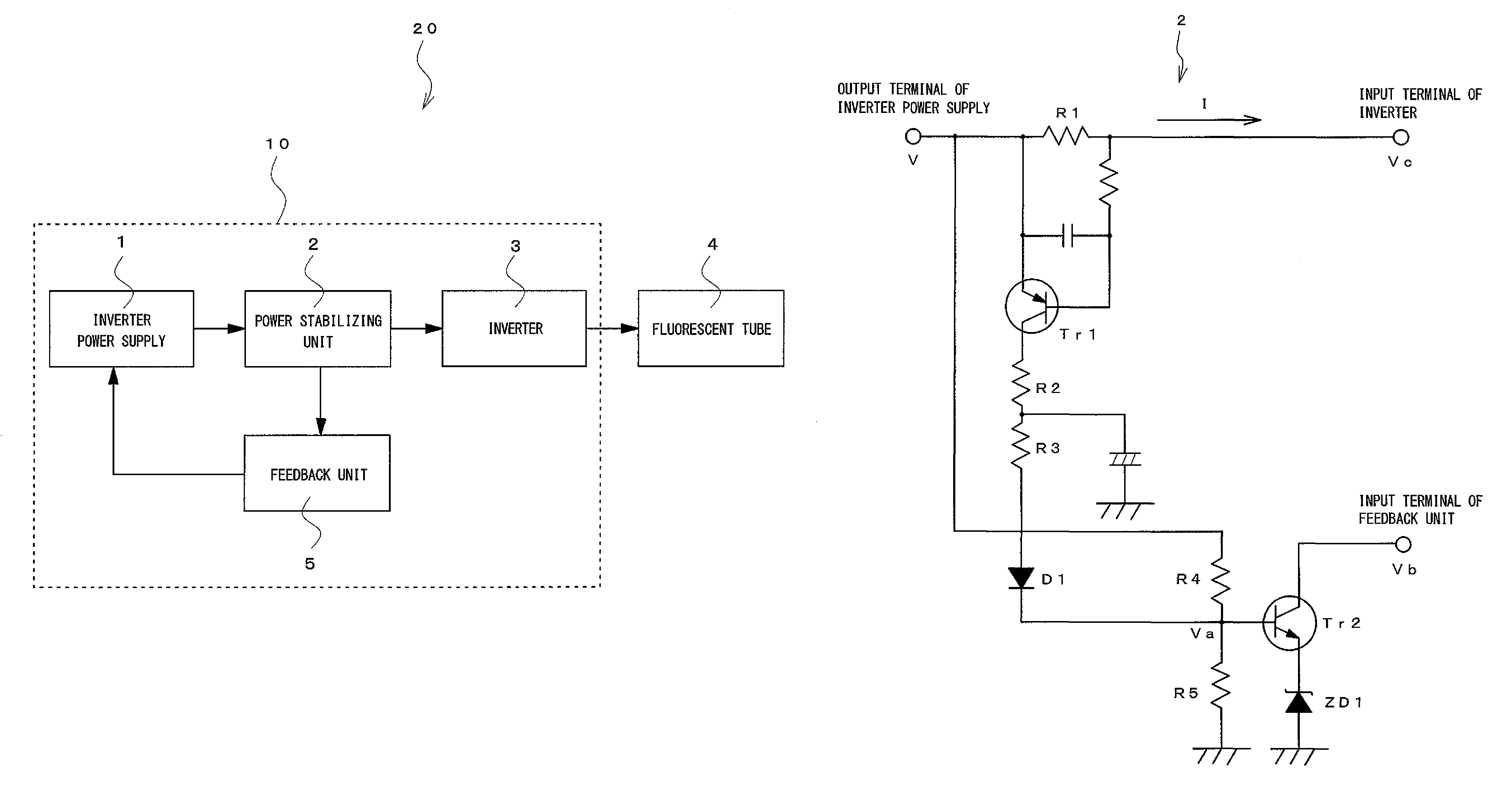
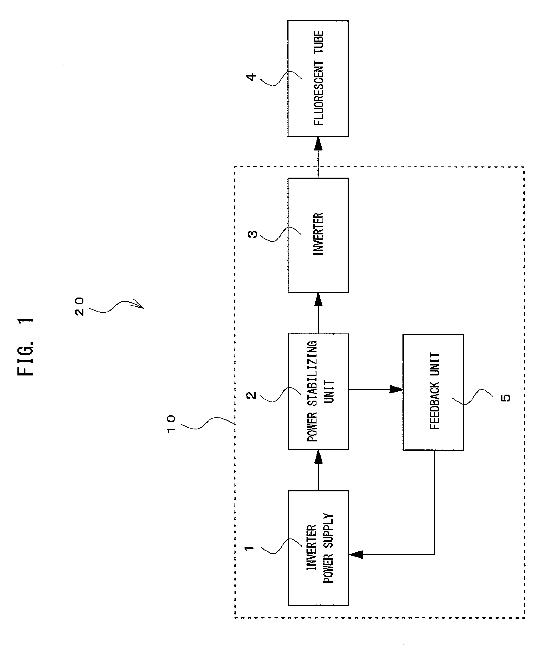
[0041]FIG. 1 is a block diagram of a backlight according to the embodiment of the present invention. A backlight 20 includes an inverter power supply 1 for converting a domestic commercial power supply, that is, an AC power supply to a DC power supply; a power stabilizing unit 2 for stabilizing an output power of the inverter power supply 1; an inverter 3 supplied with the DC power stabilized in the power stabilizing unit 2; a fluorescent tube 4 supplied with the AC power output from the inverter 3; and a feedback unit 5 for providing a feedback control signal to the inverter power supply 1. The fluorescent tube 4 is a CCFL. The inverter power supply 1, the power stabilizing unit 2, the inverter 3, and the feedback unit 5 configure a fluorescent tube power supply 10.

[0042]The inverter power supply 1 is connected to the domestic commercial power supply (not shown) and is a DC power sup...


PUM


Abstract

A fluorescent tube power supply including an inverter power supply which outputs a DC voltage, and an inverter which converts an output of the inverter power supply to an AC; wherein a power stabilizing unit for stabilizing a power input to the inverter is arranged between the inverter power supply and the inverter; and a feedback control of the inverter power supply is performed based on an output of the power stabilizing unit. The power stabilizing unit detects a current flowing between the inverter power supply and the inverter, and the feedback control of the inverter power supply is performed based on the current.

Description

BACKGROUND OF THE INVENTION[0001]1. Field of the Invention[0002]The present invention relates to a fluorescent tube power supply and a backlight using the fluorescent tube power supply.[0003]2. Description of the Related Art[0004]Voltage and current sometimes change on a demand side due to inconsistency between a supply side that generates power, transmits power, and a demand side on which great change in load occurs. When such change occurs, power of a power supply cannot be sufficiently ensured, and electrical products may not operate properly.[0005]For instance, in a backlight used in a liquid crystal television, a direct current (DC) power supply for converting an output of a domestic commercial power supply to a direct current and an inverter for converting an output of the DC power supply to an alternating current (AC) are used as a power supply circuit. As the power input to the inverter reduces, the brightness of a screen becomes less than the preset brightness. As the power...

Claims


Application Information

Patent Timeline
Patent Type & Authority Patents(United States)
IPC IPC(8): G05F1/00F21Y103/37
CPCH05B41/2821
Inventor MIYAMOTO, HITOSHIJINNOUCHI, TAKASHI
Owner FUNAI ELECTRIC CO LTD
Why Eureka
Try Eureka