Stress luminescence measurement device and stress luminescence measurement method

a luminescence measurement and stress technology, applied in the direction of force measurement by measuring optical property variation, material strength using steady bending force, instruments, etc., can solve problems such as sample breakage, and achieve the effect of verifying the durability and the performance of the sampl

Inactive Publication Date: 2021-11-18
SHIMADZU CORP
View PDF0 Cites 0 Cited by
  • Summary
  • Abstract
  • Description
  • Claims
  • Application Information

AI Technical Summary

Benefits of technology

[0005]In the above-described strain measurement using a stress luminescent material, it is possible to observe the temporal change in the luminescence of the stress luminescent material due to the change in the external force applied to the sample. However, in order to verify the durability and the performance of the sample, it is required to observe the change in the luminescence of the stress luminescent material in association with an index other than the time-axis, such as, e.g., the change in the shape (e.g., the folding angle of the sample) of the sample. This is because it is useful information when verifying that the strain was generated in the sample when the sample was in a what kind of a deformation state (fold angle).

Problems solved by technology

In the above-described test, in a case where the sample has a defect, strain is generated in the periphery of the defect, which may result in a breakage of the sample.

Method used


Image

  • Stress luminescence measurement device and stress luminescence measurement method
  • Stress luminescence measurement device and stress luminescence measurement method
  • Stress luminescence measurement device and stress luminescence measurement method

Examples


embodiment 1

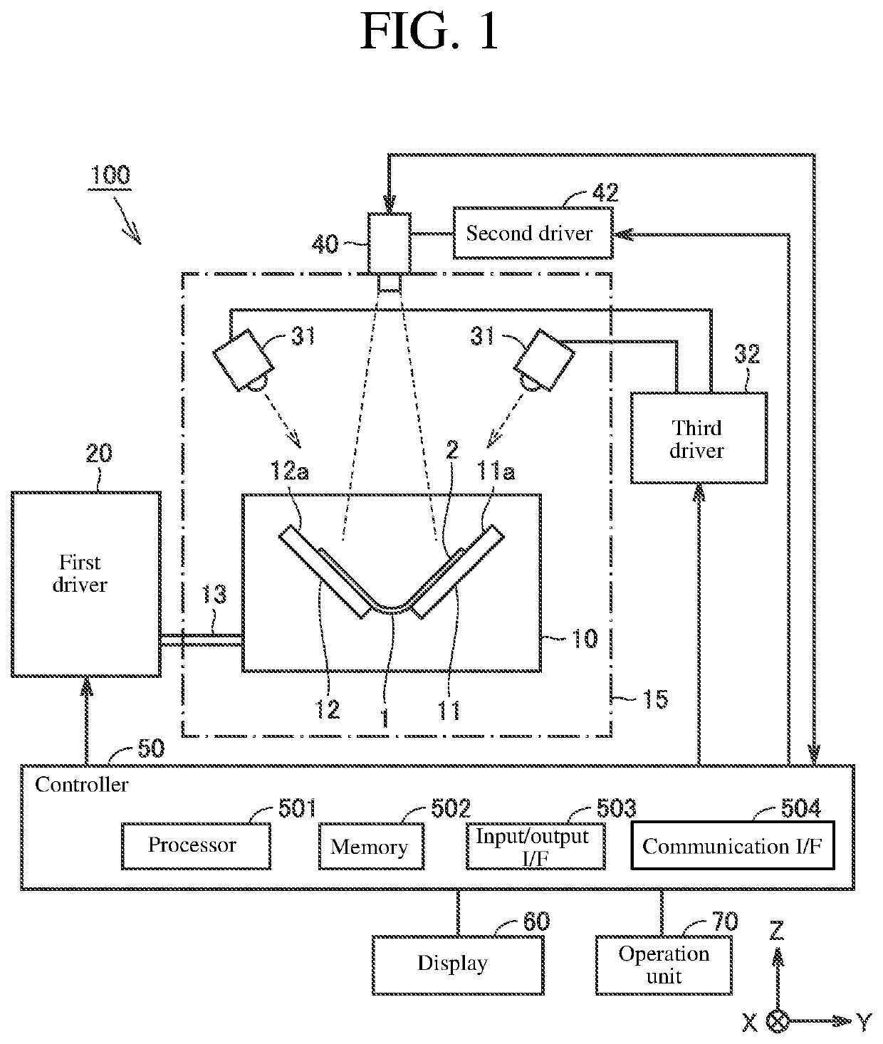
[0030]FIG. 1 is a block diagram showing the entire configuration of a stress luminescence measurement device according to Embodiment 1. The stress luminescence measurement device 100 according to Embodiment 1 is a device for measuring the stress (strain) generated in a test target 1 (hereinafter, also simply referred to as “sample”) by using a luminescence phenomenon of a stress luminescent material. The stress luminescence measurement device 100 can also be used to test the durability to the stress generated in a sample 1.

[0031]The sample 1 has flexibility and is, for example, a flexible sheet or a flexible fiber. The flexible sheet may, for example, constitute a part of a flexible display or a wearable device of a communication terminal, such as, e.g., a smartphone and a tablet. The flexible fiber may constitute, for example, a part of a optical-fiber cable.

[0032]In the example of FIG. 1, the sample 1 is a rectangular flexible sheet. A stress luminescent material 2 is arranged on ...

embodiment 2

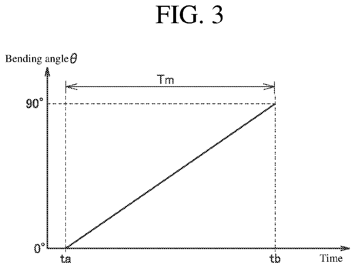
[0097]In Embodiment 1, an example is shown in which based on the relational expression or table (see FIG. 3) acquired in advance, the bending angle θ of the sample at the imaging timing is calculated, but it may be configured to calculate the bending angle θ of the sample 1 from the captured image P1 by the camera 40.

[0098]In Embodiment 2, a method of calculating the bending angle θ of the sample 1 from the captured image P1 will be described. Note that in Embodiment 2 and thereafter, the configuration of the stress luminescence measurement device 100 is the same as the configuration of the stress luminescence measurement device 100 shown in FIG. 1, and therefore, the description will not be repeated. Further, since the processing procedures of the stress luminescence measurement are the same as the flowchart shown in FIG. 5 except for a step for acquiring the bending angle θ of the sample 1 (S40 in FIG. 5), the detailed description will not be repeated.

[0099]FIG. 9 is a diagram for...

embodiment 3

[0107]In a stress luminescence measurement method according to Embodiment 3, the imaging timing by the camera 40 is set in accordance with the bending angle θ of the sample 1. FIG. 10 is a timing chart for explaining the operations of the light source 31, the camera 40, and the holder 10 in the stress luminescence measurement device 100 according to Embodiment 3. In FIG. 10, a waveform showing the irradiation timing of excitation light in the light source 31, a waveform showing the imaging timing of the camera 40, and a waveform showing the operation timing of the holder 10 by the first driver 20 are shown.

[0108]As shown in FIG. 10, when the imaging by the camera 40 is started at the time t3, the number of still images corresponding to the frame rate of the camera 40 is generated. In Embodiment 3, the test is stopped every frame, and the sample 1 is imaged by the camera 40 in a state in which the bending angle θ is maintained at the stopped timing.

[0109]Specifically, by dividing the...


PUM

PropertyMeasurementUnit
bending angleaaaaaaaaaa
wavelength rangeaaaaaaaaaa

Abstract

A stress luminescence measurement device according to a first aspect is provided with a load application mechanism configured to deform a sample by applying a load to the sample, a light source configured to emit excitation light to a stress luminescent material 2 arranged on a surface of the sample, a camera configured to image luminescence of the stress luminescent material, and a controller configured to control the load application mechanism, the light source, and the camera. The controller acquires a deformation state of the sample at the imaging timing by the camera and stores the acquired deformation state of the sample in association with the image captured by the camera in a memory.

Description

CROSS-REFERENCE TO RELATED APPLICATIONS[0001]This application claims priority under 35 U.S.C. § 119 to Japanese Patent Application No. 2020-084530 filed on May 13, 2020, the entire disclosure of which is incorporated herein by reference in its entirety.BACKGROUND OF THE INVENTIONField of the Invention[0002]The present invention relates to a stress luminescence measurement device and a stress luminescence measurement method.Description of the Background Art[0003]In a development side of a flexible device, it is a common practice to verify the durability and the performance of a sample by repeatedly applying a load to the sample using a deformation test instrument. In the above-described test, in a case where the sample has a defect, strain is generated in the periphery of the defect, which may result in a breakage of the sample.[0004]In recent years, as a technique for detecting such a defect, a technique using a stress luminescent material has been proposed. For example, Japanese Un...

Claims


Application Information

Patent Timeline
Patent Type & Authority Applications(United States)
IPC IPC(8): G01N21/70G01N3/32G01L1/24
CPCG01N21/70G01L1/24G01N3/32G01N3/02G01N3/08G01B11/16G01N3/20G01N2203/006G01N2203/0647G01N2203/0282G01N2203/0023G01N2203/0005
Inventor YOKOI, YUSUKEYAMAKAWA, MOMOYOFUJIWARA, NAOYATSUSHIMA, HIROAKIADACHI, KENTA
Owner SHIMADZU CORP
Why Eureka
Try Eureka