
Commercial vehicle exhaust brake valve high-temperature durability test device and method
An exhaust brake valve, durability test technology, applied in the direction of mechanical valve testing, etc., can solve the problems of inability to accurately simulate the working conditions and environment, difficult adjustment and control of test conditions, low accuracy of test results, etc., to achieve real-time Detection and control, reduced test cycle, high accuracy effect
- Summary
- Abstract
- Description
- Claims
- Application Information
AI Technical Summary
Problems solved by technology
Method used
Image

Examples
Embodiment Construction
[0031] The present invention will be further described in detail below in conjunction with the accompanying drawings and specific embodiments to facilitate a clear understanding of the present invention, but they do not limit the present invention.
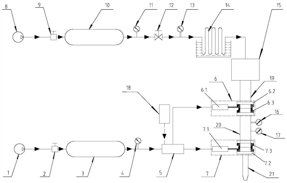
[0032] Such as figure 1 The high-temperature durability test device for a commercial vehicle exhaust brake valve includes a power control unit and a compressed air heating unit; the power control unit includes a first air source 1, a first pressure reducing valve 2, a first storage Gas tank 3, first pressure gauge 4, solenoid valve 5, first exhaust brake valve 6, second exhaust brake valve 7 and electric control box 18; the first gas source 1, the first pressure reducing valve 2. The first gas storage tank 3, the first pressure gauge 4, and the solenoid valve 5 are sequentially connected. The normally closed position outlet of the solenoid valve 5 is connected to the first exhaust brake valve 6. The outlet of the solenoid valve 5 ...
PUM
 Abstract
Description
Claims
Application Information