
Oil seal durability test equipment

A durability test and oil seal technology, which is applied in machine sealing ring testing, mechanical component testing, machine/structural component testing, etc., can solve problems such as high cost, complex structure, and inability to accurately predict durability, and achieve guarantee The effect of safe operation

Pending Publication Date: 2018-02-02
SUZHOU LVKON TRANSMISSION TECH CO LTD
View PDF0 Cites 2 Cited by
  • Summary
  • Abstract
  • Description
  • Claims
  • Application Information

AI Technical Summary

Problems solved by technology

[0002] Oil seal is the main spare part of mechanical bearing equipment, which plays an important role in the operation of mechanical equipment. However, how about the durability of oil seal, the current test equipment on the market has complex structure, high cost, poor reliability and unsatisfactory simulation of actual working conditions
Its durability cannot be accurately predicted, causing unnecessary equipment damage or accidents

Method used


Image

  • Oil seal durability test equipment
  • Oil seal durability test equipment

Examples


Embodiment Construction

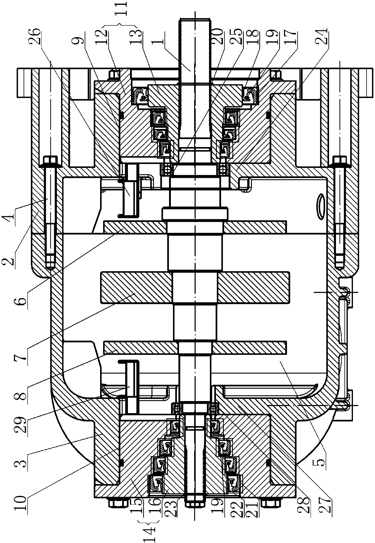
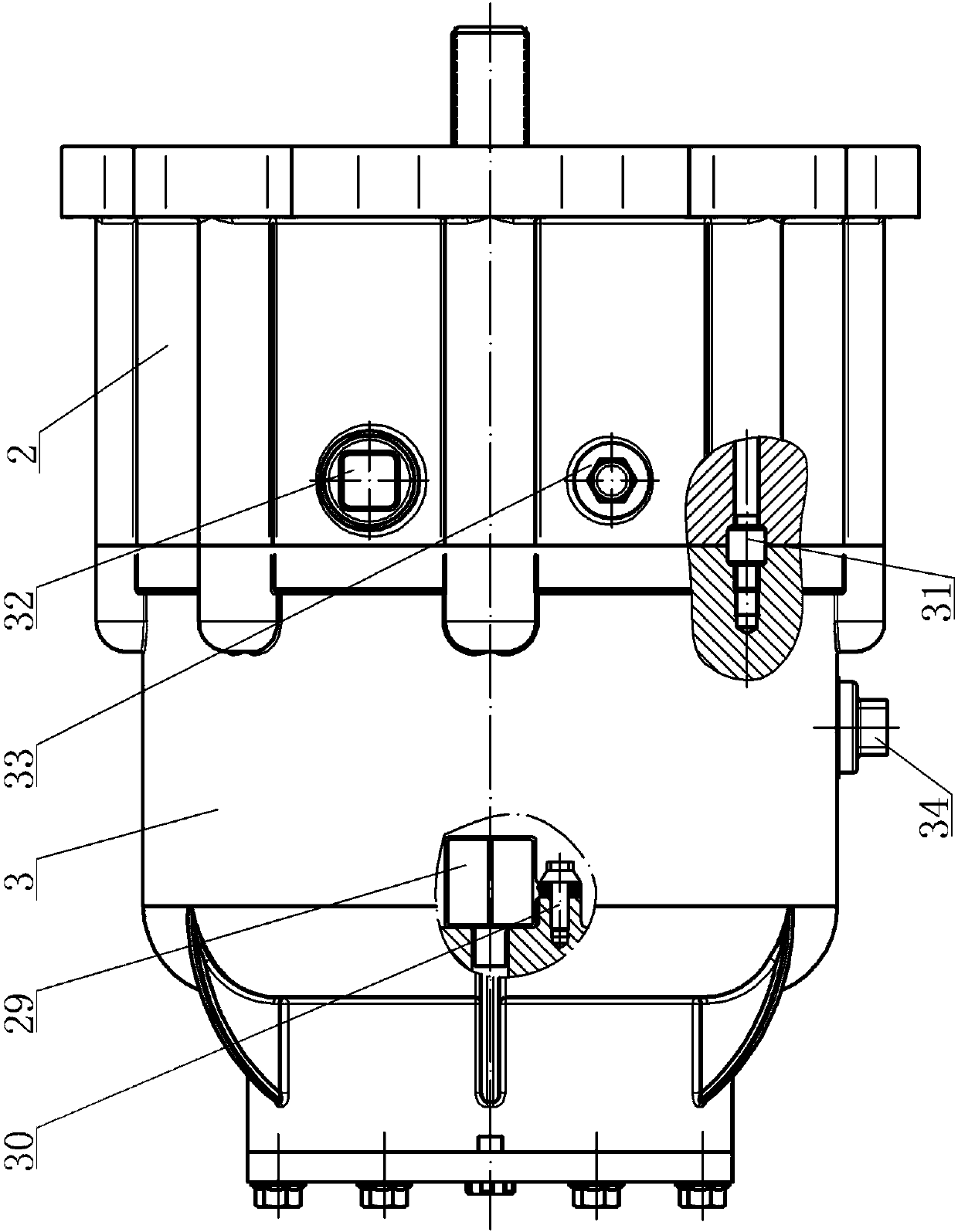
[0018] A kind of oil seal durability test equipment, see figure 1 , figure 2 : It includes a transmission shaft 1, the front end and the rear end of the transmission shaft 1 are respectively set with a front housing 2 and a rear housing 3 through bearing positioning, and the opposite annular end faces of the front housing 2 and the rear housing 3 pass through the box positioning flange 4. Tightly connected, the front housing 2 and the rear housing 3 are combined to form a central cavity 5, and the position of the transmission shaft 1 corresponding to the central cavity 5 is arranged at intervals with a front oil throwing plate 6, an inertia plate 7, and a rear oil throwing plate. Disc 8, the center of the front end of the front housing 2 is indented to form a positioning cavity 9 for the front quick change sleeve, the center of the rear end of the rear housing 3 is indented to form a positioning cavity 10 for the rear quick change sleeve, and the front quick change sleeve 11 ...


PUM


Abstract

The invention provides oil seal durability test equipment. The equipment can simulate an actual working condition and carry out a bench test on oil seal durability so as to verify whether an oil sealdesign can match with an actual usage demand, verify whether an oil seal is qualified and guarantee safety operation of mechanical equipment. The equipment comprises a transmission shaft. A front endand a rear end of the transmission shaft are provided with a front shell and a rear shell through bearing positioning sleeve respectively. Opposite annular end surfaces of the front shell and the rearshell are fastened and connected through a box body positioning flange. The front shell and the rear shell are combined and then form a center cavity. A position of the transmission shaft, which corresponds to the center cavity, is provided with a front oil flinger, an inertia disc and a rear oil flinger at intervals. A front end center of the front shell is recessed inwardly so as to form a front quick-change sleeve positioning chamber, and a rear end center of the rear shell is recessed inwardly so as to form a rear quick-change sleeve positioning chamber. A front quick-change sleeve comprises a front quick-change sleeve shell and a front quick-change sleeve shaft. A rear quick-change sleeve comprises a rear quick-change sleeve shell and a rear quick-change sleeve shaft.

Description

technical field [0001] The invention relates to the technical field of oil seal testing, in particular to an oil seal durability test equipment. Background technique [0002] Oil seal is the main spare part of mechanical bearing equipment, which plays an important role in the operation of mechanical equipment. However, the durability of oil seal is the current test equipment on the market with complex structure, high cost, poor reliability and unsatisfactory simulation of actual working conditions. Its durability cannot be accurately predicted, causing unnecessary equipment damage or accidents. Contents of the invention [0003] In view of the above problems, the present invention provides an oil seal durability test equipment, which can simulate the actual working conditions to conduct a bench test on the durability of the oil seal, so as to understand the service life of the oil seal and ensure the safe operation of mechanical equipment. [0004] An oil seal durability ...

Claims


Application Information

Patent Timeline
IPC IPC(8): G01M13/00
CPCG01M13/005Y02E30/30
Inventor 李磊杨海华吴茂瑞王康林蒋尧陈家炜
Owner SUZHOU LVKON TRANSMISSION TECH CO LTD
Learn More