Detector System with Positioning System

a positioning system and detector technology, applied in the field of detector modules, can solve the problems of inability to centralize the surveillance of different locations or require additional technical equipmen

Active Publication Date: 2010-01-14
FLIR DETECTION
View PDF7 Cites 44 Cited by
  • Summary
  • Abstract
  • Description
  • Claims
  • Application Information

AI Technical Summary

Benefits of technology

The patent text describes a new detector module that uses LED stabilization and calibration, instead of requiring radioactive radiation sources. This means that the detector module can be more easily and accurately stabilized and calibrated.

Problems solved by technology

The patent text discusses the use of detector systems for measuring ionizing radiation. However, these systems have the disadvantage of requiring multiple detector systems to monitor different locations, which can be costly and difficult to manage. Additionally, it can be difficult to determine the position of these detector systems, especially when they are mobile or handheld. The technical problem addressed in this patent is to provide a more cost-effective and efficient way to monitor different locations with a single detector system.

Method used


Image

  • Detector System with Positioning System
  • Detector System with Positioning System
  • Detector System with Positioning System

Examples


Embodiment Construction

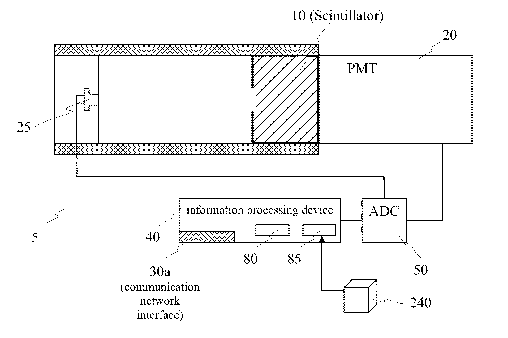
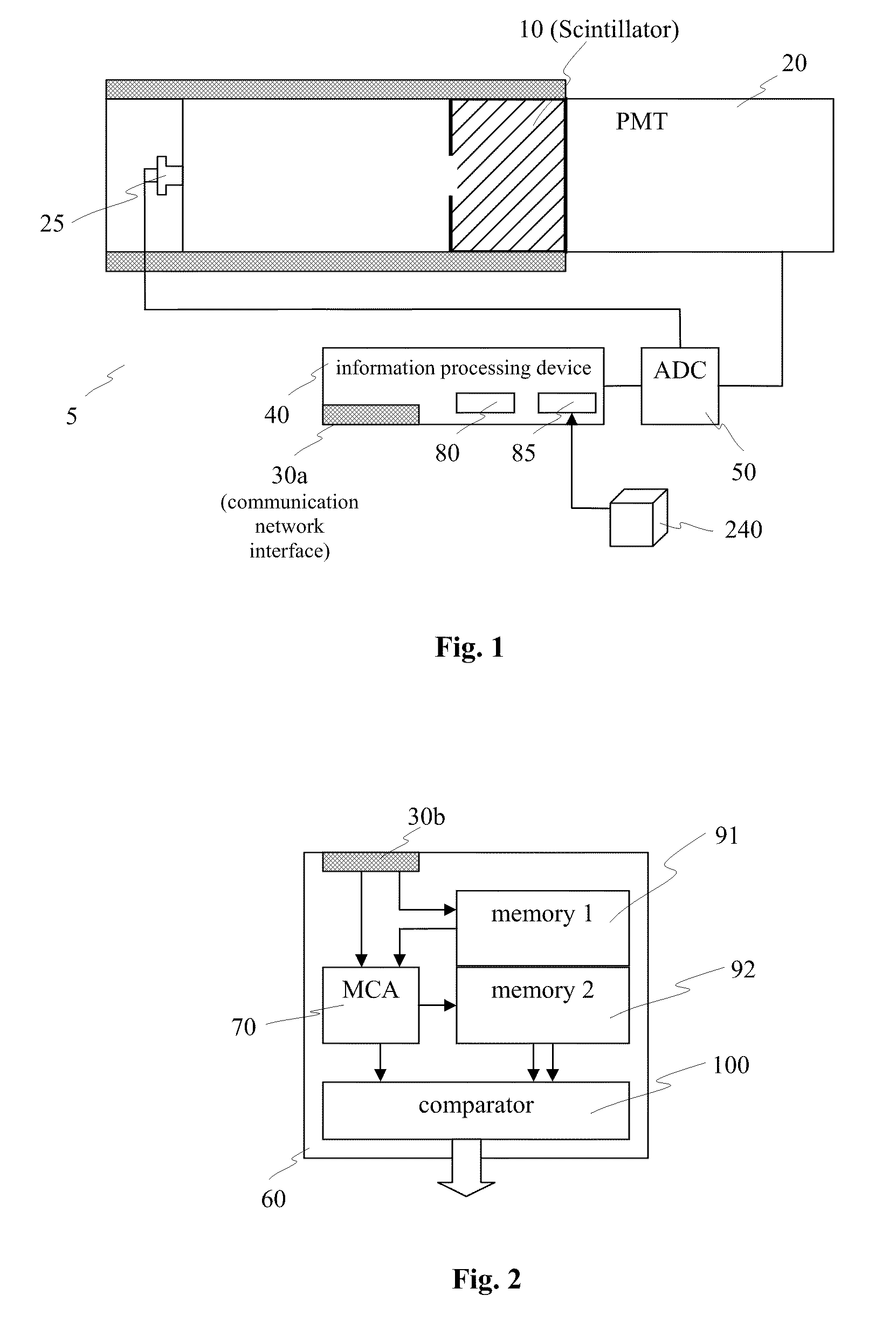
[0035]In FIG. 1, the main elements of a detector module can be seen, that is[0036]a) a detector unit 5 consisting of scintillation crystal 10, a photomultiplier 20 with a photocathode, serving as a light detector, and an LED 25, used for stabilizing the detector unit,[0037]b) an information processing device 40 coupled to an analog to digital converter (ADC) 50,[0038]c) a memory device 85 for storing the position of the detector module,[0039]d) a communication network interface 30a, and[0040]e) an (optional) location determination device, such as Global Positioning System (GPS) or the like.

[0041]Radiation (e.g. γ-radiation) enters the scintillation crystal 10 and is absorbed within this scintillation crystal. An excited state, following the absorption from the radiation, decays under the emission of light. The light is then directed to the photocathode, which, as a consequence of the light absorption, is emitting electrons. The resulting electric signal is amplified within the photo...


PUM


Abstract

Provided is a detector module for measuring one or more types of radiation, in particular X-ray, gamma ray, or nuclear particle radiation, comprising a detection unit, an analog-to-digital converter, an information processing device, and a memory device for storing the position of the detector module. The detector module comprises at least one light-emitting diode (LED), optically connected with the detection unit for stabilizing the detector unit. Further, the invention provides a stanchion, in particular a portable stanchion, whereby the stanchion comprises a inventive detector module. Yet further, a (wireless) network of detector modules is provided, whereby each detector module is mounted within a stanchion.

Description


Claims


Application Information

Patent Timeline
Owner FLIR DETECTION
Why Eureka
Try Eureka