Bit holder

Inactive Publication Date: 2010-01-14
CHEN HO TIEN
View PDF23 Cites 4 Cited by
  • Summary
  • Abstract
  • Description
  • Claims
  • Application Information

AI Technical Summary

Benefits of technology

[0019]The object of this invention is to offer a bit holder adapted to a screw band of an automatic screwdriver with a small outer diameter (less than 7 mm). The bit holder can permit its bit quickly changed, with a tolerance of a gap between the bit and a shank minimized, enabling the bit not to swing so that it can drive a screw smoothly into an object.
[0024]4. In combining the bit with the bit holder, the bit is inserted through the through hole of the bit sleeve, and then the male threads of the bit sleeve are engaged with the female threads of the shank. Then an auxiliary tool is fitted around the circular circumference, and the bit sleeve is rotated to combine threadably with the combining hole of the shank, with the lower portion of the bit sleeve pressing an upper portion of the bit so as to minimize the tolerance of the gap between the bit and the shank. Thus the bit never swings so that the bit can drive a screw effectively and smoothly into an object.

Problems solved by technology

The conventional bit holders shown in FIGS. 1˜3 has a rather large outer diameter (more than 7 mm), unsuitable for being utilized in an automatic screwdriver with a screw band.
But, with the hole 15 bored in the shank 1, the strength of the shank 1 is to be downgraded, apt to make the shank 1 deformed or broken at the location of the hole 15, posing a loss or a burden to consumers.
However, as the outer diameter (d1) of the sliding sleeve 14A is much larger than the outer diameter (d2) of the shank 1, such a two-part-assembled bit holder can hardly be utilized in an automatic screwdriver.
But, because the circumference of the bit holder is wrapped by screw band holes and their annular circumference, the relevant component of the automatic screwdriver is difficult to come back to its original position owing to a large diameter of the bit holder.
Moreover, as the bit sleeve 3 is made of plastics, a rather great tolerance is practically created in engagement of the bit sleeve 3 and the bit 2, posing an unacceptable gap between the bit 2 and the shank 1 so that the bit 2 is to swing while being driven to rotate with a high speed by a hand tool, unable to smoothly and precisely drive a screw into an object.

Method used


Image

  • Bit holder
  • Bit holder
  • Bit holder

Examples


Embodiment Construction

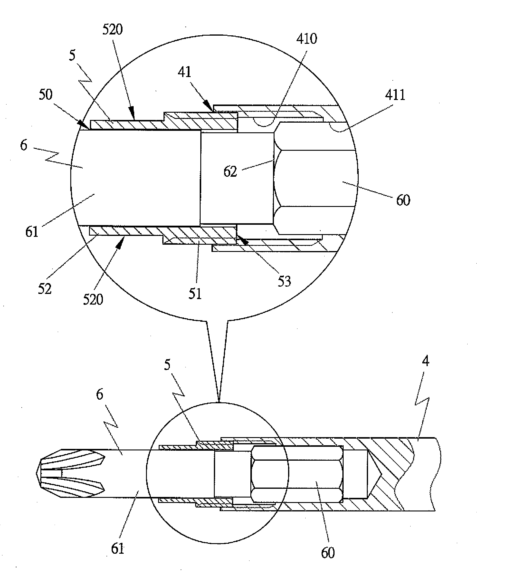
[0041]As shown in FIGS. 79, a preferred embodiment of a bit holder in the present invention includes a shank 4, and a bit sleeve 5.

[0042]The shank 4 is provided with a non-circular geometric first end portion 40 for being engaged with a hand tool, and a second end portion formed with a combining hole41. As shown in FIG. 10, the combining hole 41 is provided with female threads 410 formed around its partial inner wall for being engaged with the bit sleeve 5, and a polygonal surface 411 also formed around its partial inner wall for corresponding to a combining portion 60 of a bit 6.

[0043]The bit sleeve 5, as shown in FIGS. 10˜13, is provided with a through hole 50 for the bit 6 to penetrate through, male threads 51 formed around its rear portion for engaging with the female threads 410 of the combining hole 41 of the shank 4, and a circular circumference 52 for being twisted by an auxiliary tool 7 to keep the bit sleeve 5 fixed in or loosened from the combining hole 41 of the shank 4 ...


PUM


Abstract

A bit holder includes a shank, and a bit sleeve. The shank has a first end portion of a non-circular geometric equiangular cross-section for combining a hand tool, and a second end portion formed with a combining hole having female threads in its wall. The bit sleeve has a through hole for a bit to extend therein, male threads and a circular circumference. The bit sleeve is combined with the shank by engagement of the male threads with the female threads, and the bit sleeve may be rotated to fix with or loosen from the shank by an auxiliary tool for changing the bit. In assembling, the bit is inserted through the through hole of the bit sleeve, and then the male threads of the bit sleeve are engaged with the female threads of the shank by an auxiliary tool fitted with the circular circumference and rotated to keep the bit combined with the shank, with the bit sleeve pressing the bit so as to minimize the tolerance of the gap between them, thus enabling the bit to drive a screw smoothly into an object.

Description

BACKGROUND OF THE INVENTION[0001]1. Field of the Invention[0002]This invention relates to a bit holder, particularly to one including a shank provided with a combining hole, and a bit sleeve provided with a through hole. In combining a bit with the bit holder, the bit is inserted through the through hole of the bit sleeve, and then the male threads of the bit sleeve are engaged with the female threads of the shank. Then an auxiliary tool is fitted around a circular circumference of the bit sleeve, which is successively rotated to combine threadably with the combining hole of the shank, with the lower portion of the bit sleeve pressing an upper portion of the bit so as to minimize the tolerance of the gap between the bit and the shank. Thus the bit sleeve never departs from the shank, and the bit never swings so that the bit can drive a screw effectively and smoothly into an object.[0003]2. Description of the Prior Art[0004]FIGS. 1˜3 show three sorts of conventional bit holders, whic...

Claims


Application Information

Patent Timeline
IPC IPC(8): B23B31/11
CPCB23B31/11B25B23/0035Y10T279/17948Y10T279/17931Y10T279/17881Y10T279/16Y10T279/3406
Inventor CHEN, HO-TIEN
Owner CHEN HO TIEN
Why Eureka
Try Eureka