Imaging apparatus and imaging condition setting method and program

Active Publication Date: 2013-11-21
CANON KK
View PDF5 Cites 5 Cited by
  • Summary
  • Abstract
  • Description
  • Claims
  • Application Information

AI Technical Summary

Benefits of technology

The present invention provides a way to quickly set the settings for an imaging device, which can help to get correct results even if there are some mistakes in the initial settings. The invention includes a method and program for the imaging device.

Problems solved by technology

This configuration is difficult to discriminate objects having similar appearances.
This may increase the amount of calculations and take a long time for the calculation for setting a new imaging condition.
The high number of possible patterns of internal states during the calculation makes advance calculation and caching difficult.
Thus, the method described in NPL 1 is difficult to quickly set an imaging condition.

Method used


Image

  • Imaging apparatus and imaging condition setting method and program
  • Imaging apparatus and imaging condition setting method and program
  • Imaging apparatus and imaging condition setting method and program

Examples


first embodiment

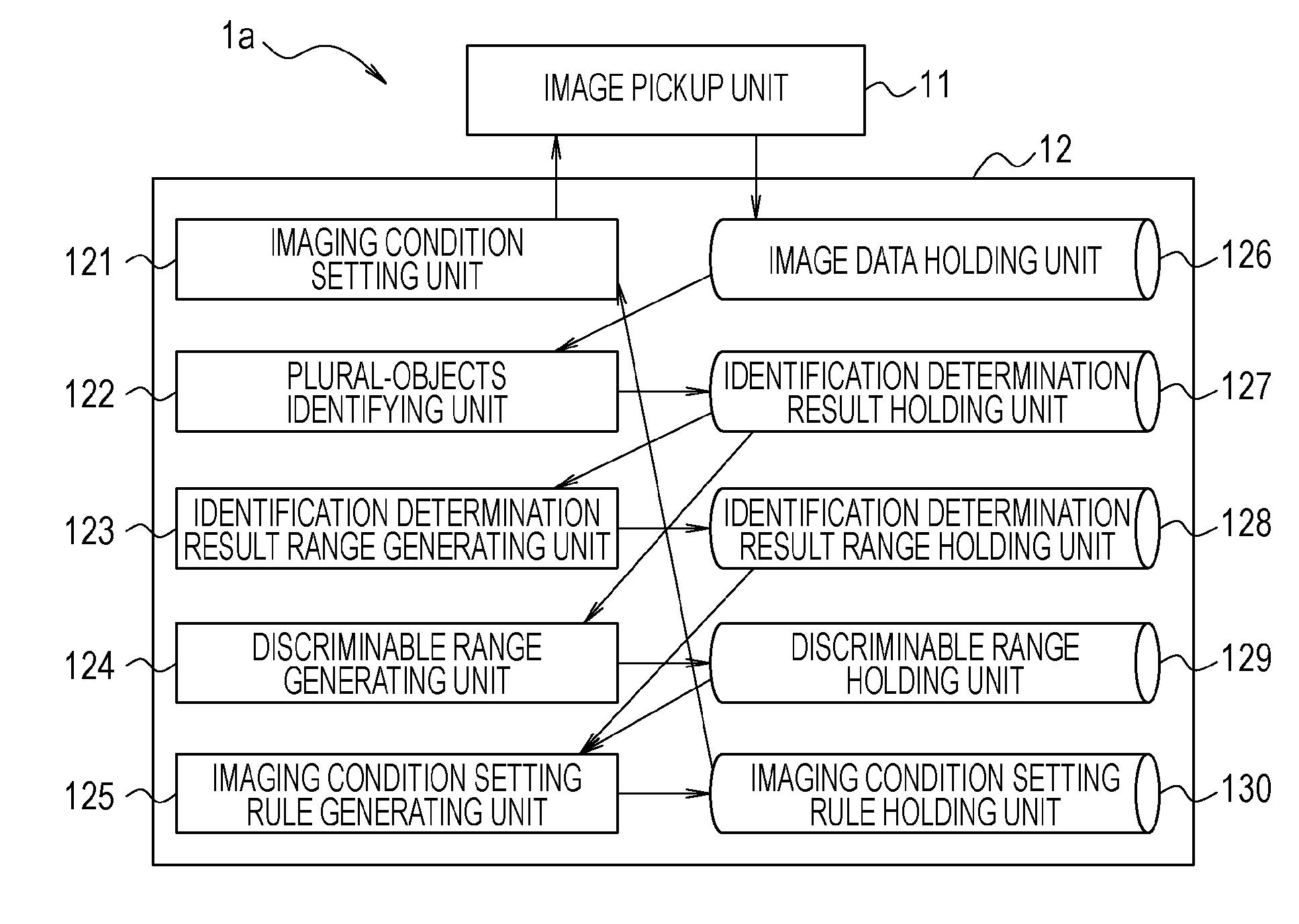
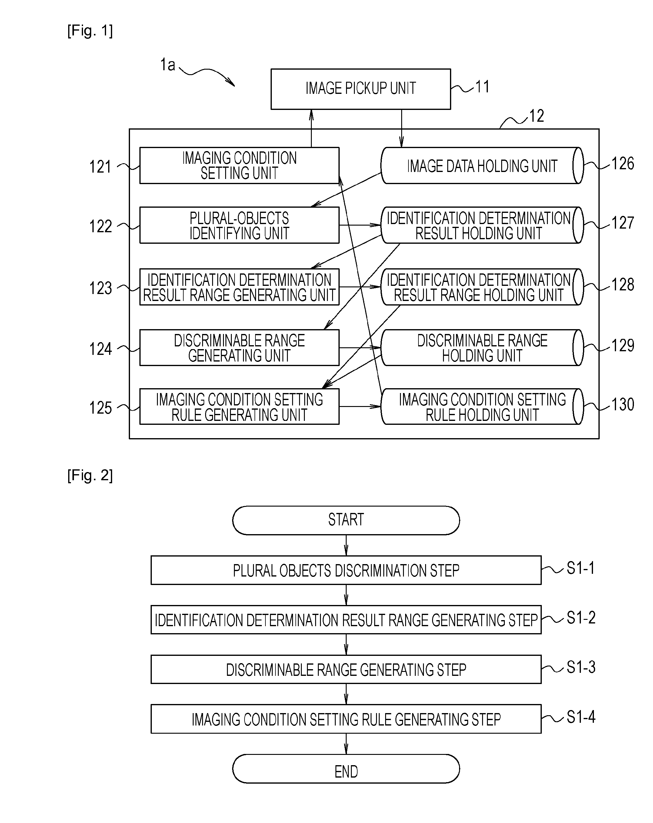
[0029]A first embodiment of the present invention will be described in detail with reference to drawings. The first embodiment of the present invention may discriminate objects which may have similar appearances from a plurality of directions that are mutually different. FIG. 1 is a block diagram illustrating an entire configuration of an imaging apparatus of a first embodiment of the present invention or an image pickup system 1a of the first embodiment (hereinafter called a “first imaging apparatus”1a).

[0030]As illustrated in FIG. 1, the first imaging apparatus 1a includes an image pickup unit 11 which may image an object and generate image data and a calculating unit 12 which may perform various types of calculation. The calculating unit 12 has an imaging condition setting unit 121, a plural-objects discriminating unit 122, an identification determination result range generating unit 123, a predetermined generating unit, and a predetermined holding unit. The predetermined generat...

second embodiment

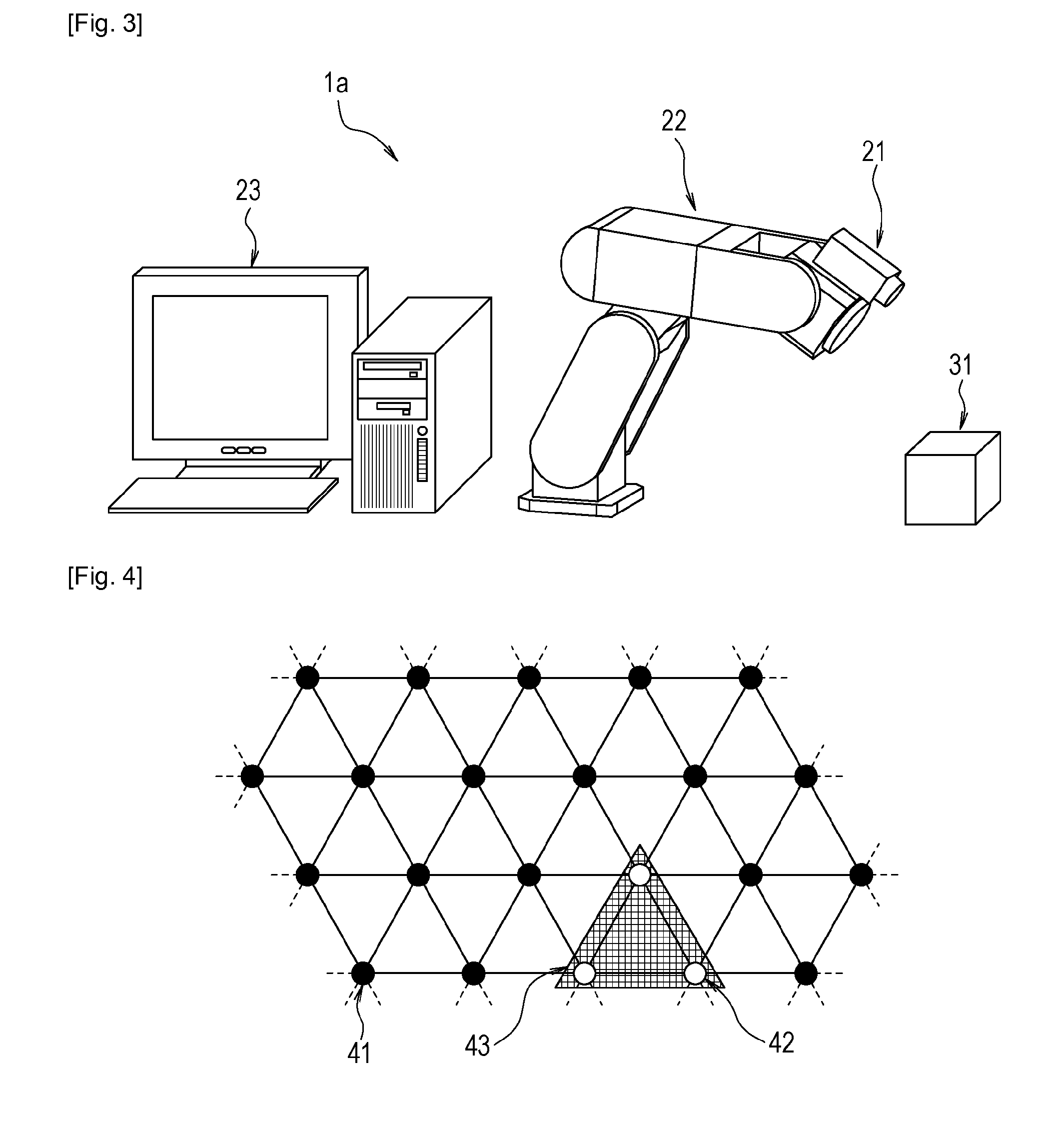
[0053]Next, a second embodiment of the present invention will be described. A second embodiment of the present invention discriminates mutually different objects having similar appearances. Differences from the first embodiment of the present invention will be described mainly, and the description of some common matters to the first embodiment of the present invention will be omitted. The same configuration as that of the first imaging apparatus is applicable (see FIG. 1) to an imaging apparatus of the second embodiment of the present invention or an image pickup system (hereinafter called a “second imaging apparatus”) according to the second embodiment. A specific configuration of the second imaging apparatus may also be the same as that of the first imaging apparatus (see FIG. 3).

[0054]FIG. 8 is a flowchart illustrating a processing flow of an imaging condition setting method and program of the second embodiment of the present invention. The processing flow of the imaging conditio...

third embodiment

[0064]Next, a third embodiment of the present invention will be described. The third embodiment of the present invention uses an illumination which radiates light to an object. The entire configuration of an imaging apparatus of the third embodiment of the present invention or an image pickup system 1c of the third embodiment of the present invention (hereinafter called a “third imaging apparatus”1c) may apply the same configuration as that of the first imaging apparatus 1a (see FIG. 1). The processing flow for generating an imaging condition setting rule according to the third embodiment of the present invention may apply the processing flow illustrated in FIG. 2. However, the specific configuration of the third imaging apparatus 1c and the specific steps of the processing flow for generating an imaging condition setting rule according to the third embodiment of the present invention are different from the first embodiment. Differences from the first embodiment of the present inven...


PUM


Abstract

According to the present invention, an imaging condition setting method includes an object discriminating step S1-1 of discriminating the object by using images, a discriminable range generating step S1-2 of generating a discriminable range that is a range of the imaging conditions under which the object is discriminable, an identification determination result range generating step S1-2 of generating an identification determination result range that is a range of the imaging conditions under which the objects are determined as identical, an imaging condition setting rule generating step S1-4 of generating an imaging condition setting rule that is a rule for changing an imaging condition by using the discriminable range and the identification determination result range, and an imaging condition setting step S2-4 of setting an imaging condition under which the object is discriminable by using the imaging condition setting rule generated by the imaging condition setting rule generating step.

Description

TECHNICAL FIELD[0001]The present invention relates to imaging apparatuses and imaging condition setting methods and programs.[0002]In particular, the present invention relates to an imaging apparatus which discriminates the position, posture, or type, for example, of an object by using image data captured by imaging of the object and an imaging condition setting method and program which are preferable for imaging an object with the imaging apparatus.BACKGROUND ART[0003]In recent years, the demands for causing robots to perform works have grown, such as assembly works in factories. A robot handling an object without a fixed position, posture or type, for example, may require a device for measuring the position, posture or type, for example, of the object. A visual sensor may be widely used as the device for measuring the position, posture or type, for example, of the object.[0004]Causing a robot to perform a work such as an advanced assembly work may require discrimination of an obje...

Claims


Application Information

Patent Timeline
IPC IPC(8): H04N5/232G06V10/141G03B7/00G03B17/00G06T1/00H04N5/222
CPCH04N5/23216G06V10/141G06V2201/06H04N23/60H04N23/64H04N23/62
Inventor KIURA, MIKIO
Owner CANON KK
Why Eureka
Try Eureka