
Method for testing radio frequency (RF) receiver to provide power correction data

Inactive Publication Date: 2010-01-14
LITEPOINT
View PDF34 Cites 36 Cited by
  • Summary
  • Abstract
  • Description
  • Claims
  • Application Information

AI Technical Summary

Benefits of technology

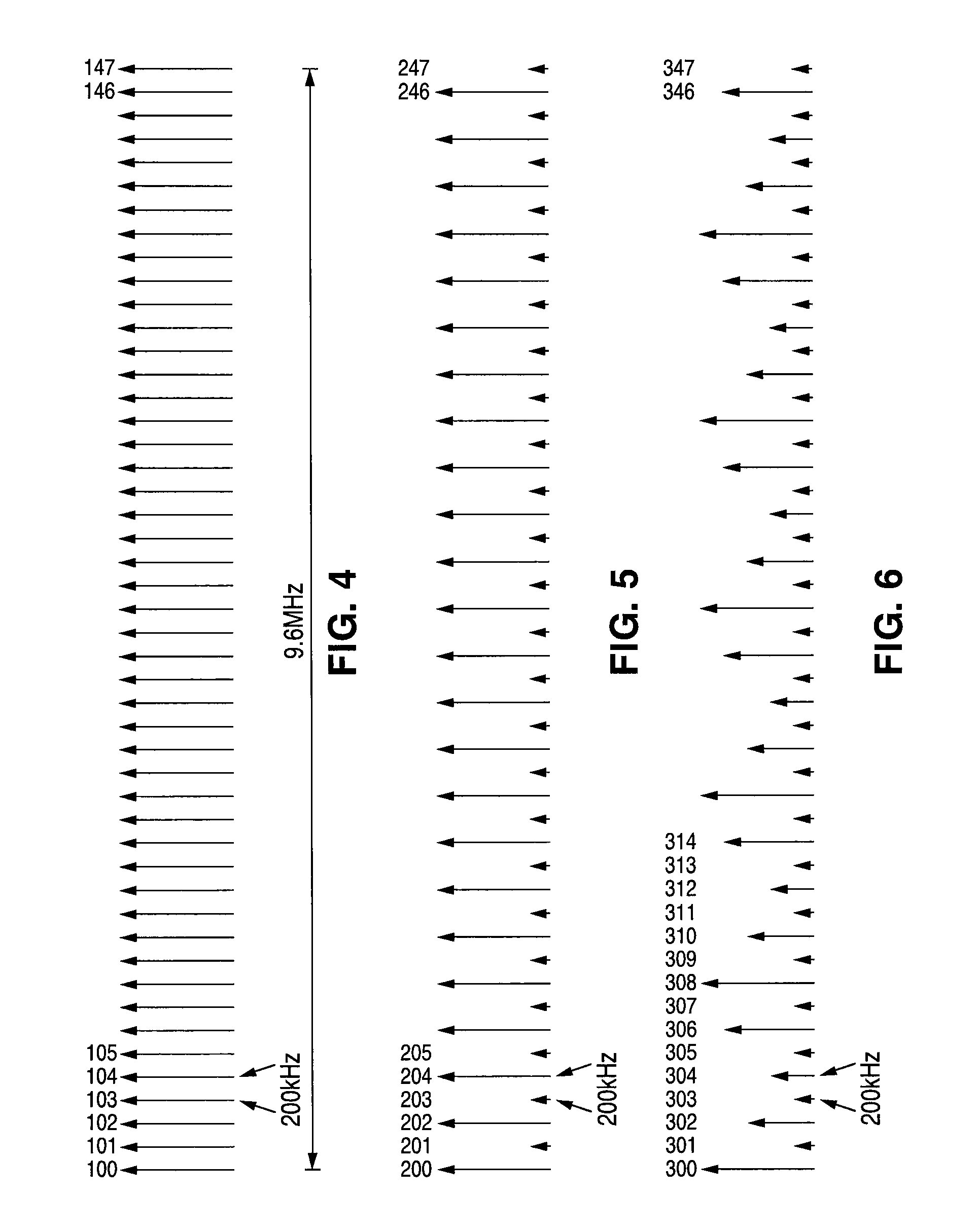
[0010]In accordance with the presently claimed invention, a method is provided for testing a radio frequency (RF) receiver as a device under test (DUT) with one or mor

Problems solved by technology

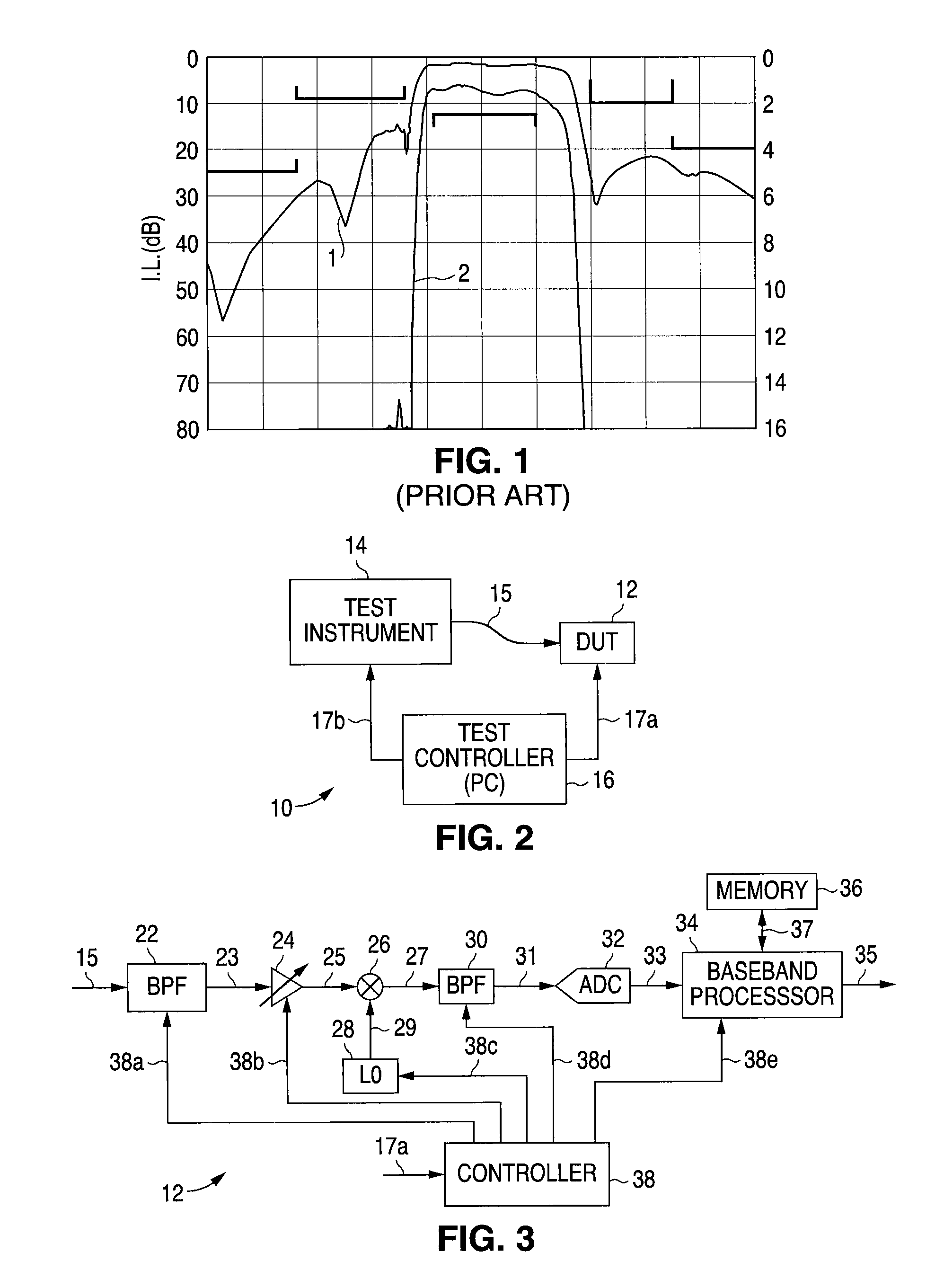
This filter attenuates out-of-band signals that otherwise would be received and processed within the receiver, and thereby use receiver resources for undesired signals, and potentially prevent proper processing of the desired in-band signals.
However, as is well known in the art, such high Q filters typically have attenuation ripple throughout the frequency pass band.
As before, since most receive measurements can be performed inside the DUT, the test time for this type of calibration is also generally limited by the speed of the test equipment.
In modern digital communication systems, for example, with high modulation accuracy requirements, this can be problematic and require more costly test equipment.

Method used


Image

  • Method for testing radio frequency (RF) receiver to provide power correction data
  • Method for testing radio frequency (RF) receiver to provide power correction data
  • Method for testing radio frequency (RF) receiver to provide power correction data

Examples


Embodiment Construction

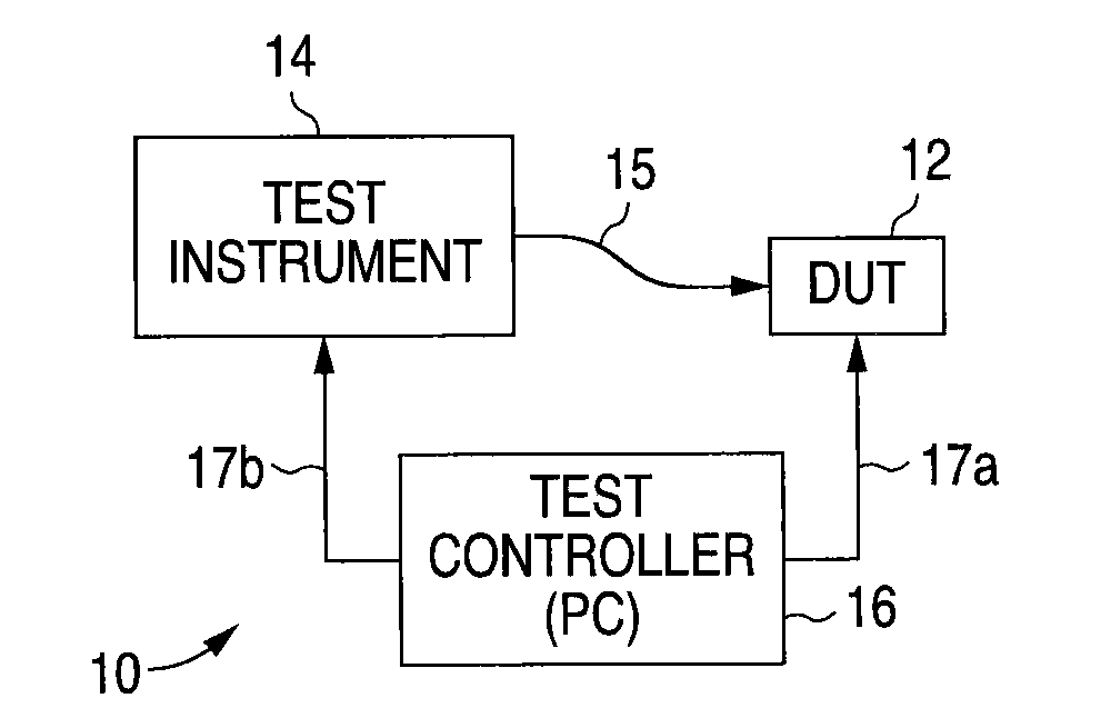
[0036]The following detailed description is of example embodiments of the presently claimed invention with references to the accompanying drawings. Such description is intended to be illustrative and not limiting with respect to the scope of the present invention. Such embodiments are described in sufficient detail to enable one of ordinary skill in the art to practice the subject invention, and it will be understood that other embodiments may be practiced with some variations without departing from the spirit or scope of the subject invention.

[0037]Throughout the present disclosure, absent a clear indication to the contrary from the context, it will be understood that individual circuit elements as described may be singular or plural in number. For example, the terms “circuit” and “circuitry” may include either a single component or a plurality of components, which are either active and / or passive and are connected or otherwise coupled together (e.g., as one or more integrated circ...


PUM


Abstract

A method for testing a radio frequency (RF) receiver as a device under test (DUT) with one or more test instruments to provide a plurality of relative power correction factors, a plurality of received signal strength indication (RSSI) calibration factors, or both.

Description

BACKGROUND[0001]1. Field of Invention[0002]The present invention relates to testing of radio frequency (RF) receivers, and in particular, to testing RF receivers to perform faster power measurements and calibrations.[0003]2. Related Art[0004]Most RF receivers, including wireless RF receivers, use an input filter, generally a band pass filter, to provide frequency band selectivity. This filter attenuates out-of-band signals that otherwise would be received and processed within the receiver, and thereby use receiver resources for undesired signals, and potentially prevent proper processing of the desired in-band signals. These filters typically have high quality factors (high Q) with relatively steep roll-off, i.e., frequency attenuation versus frequency, outside the desired frequency range. However, as is well known in the art, such high Q filters typically have attenuation ripple throughout the frequency pass band. Such ripple can often be as much as one decibel (dB) or more across ...

Claims


Application Information

Patent Timeline
IPC IPC(8): G01R35/00G01R27/32
CPCH04B17/327
Inventor OLGAARD, CHRISTIAN VOLFANDERSEN, CARSTENPETERSEN, PETEREL-HASSAN, WASSIM
Owner LITEPOINT
Learn More