Imaging apparatus

a technology of imaging apparatus and spherical lens, which is applied in the field of imaging apparatus, can solve the problems of deteriorating image quality, increasing power consumption and circuit scale, and affecting the quality of images, and achieves the effect of constant angle of view

Inactive Publication Date: 2010-01-14
OLYMPUS CORP
View PDF2 Cites 24 Cited by
  • Summary
  • Abstract
  • Description
  • Claims
  • Application Information

AI Technical Summary

Benefits of technology

[0017]According to the present invention, the magnification of the image-forming lens, the size of the read-out region, and the frame rate are controlled so that the angle of view of an image based on the imaging signal is constant. For that reason, it is possible to maintain a constant angle of view even when changing the frame rate of the imaging signal.

Problems solved by technology

However, increasing the drive speed of the imaging element or dividing the output channel into multiple lines causes degradation of image quality and leads to an increase of power consumption and circuit scale, so that there are many issues when actualizing the apparatus.
However, when performing pixel decimation of the imaging element and reading it out, a moire effect appears in the high frequency component of the photographic subject as a result of a change in the pixel pitch, and so quality of the image deteriorates.
However, in Patent Document 1, changing the size of the read-out region gives rise to the problem of the angle of field of the image based on the imaging signal changing.

Method used


Image

  • Imaging apparatus
  • Imaging apparatus
  • Imaging apparatus

Examples


first embodiment

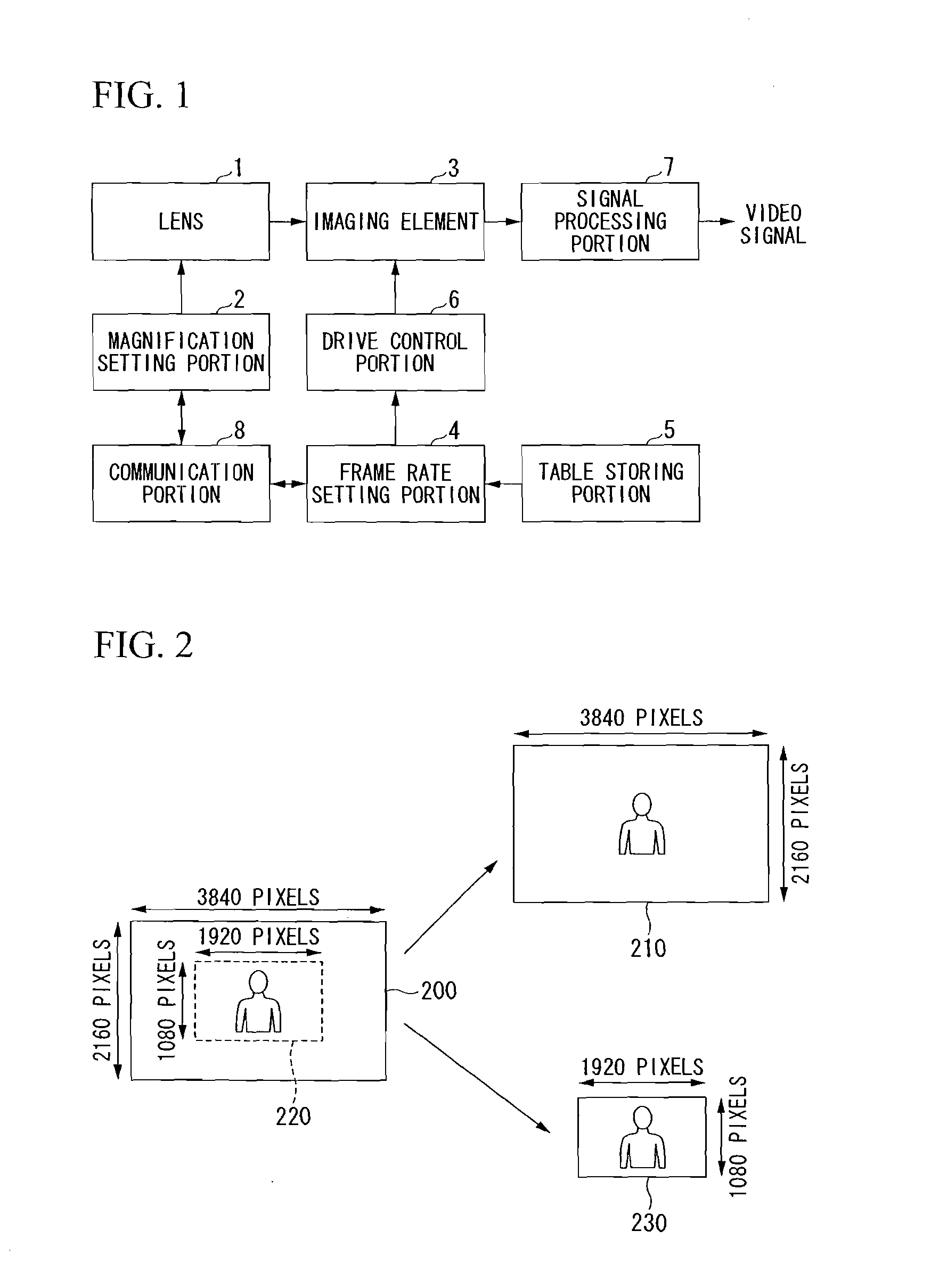
[0037]First, the first embodiment of the present invention will be described. FIG. 1 shows the constitution of the imaging apparatus in accordance with the present embodiment. In FIG. 1, a lens 1 (image-forming lens) is a lens provided with for example a zoom mechanism that includes a variable power optical system (not shown), and condenses light from a photographic subject (not shown) and forms an image. In addition to a zoom mechanism, one that has a variable power mechanism such as an extender or a converter may be applied to the lens 1. The image that is formed by the lens 1 enters an imaging element 3.

[0038]A magnification setting portion 2 controls imaging magnification by controlling the variable power optical system of the lens 1. The photographer can input the magnification of the lens 1 desired to be set into the magnification setting portion 2. The imaging element 3 (imaging part) is an XY address type solid-state imaging element that is capable of performing block readin...

second embodiment

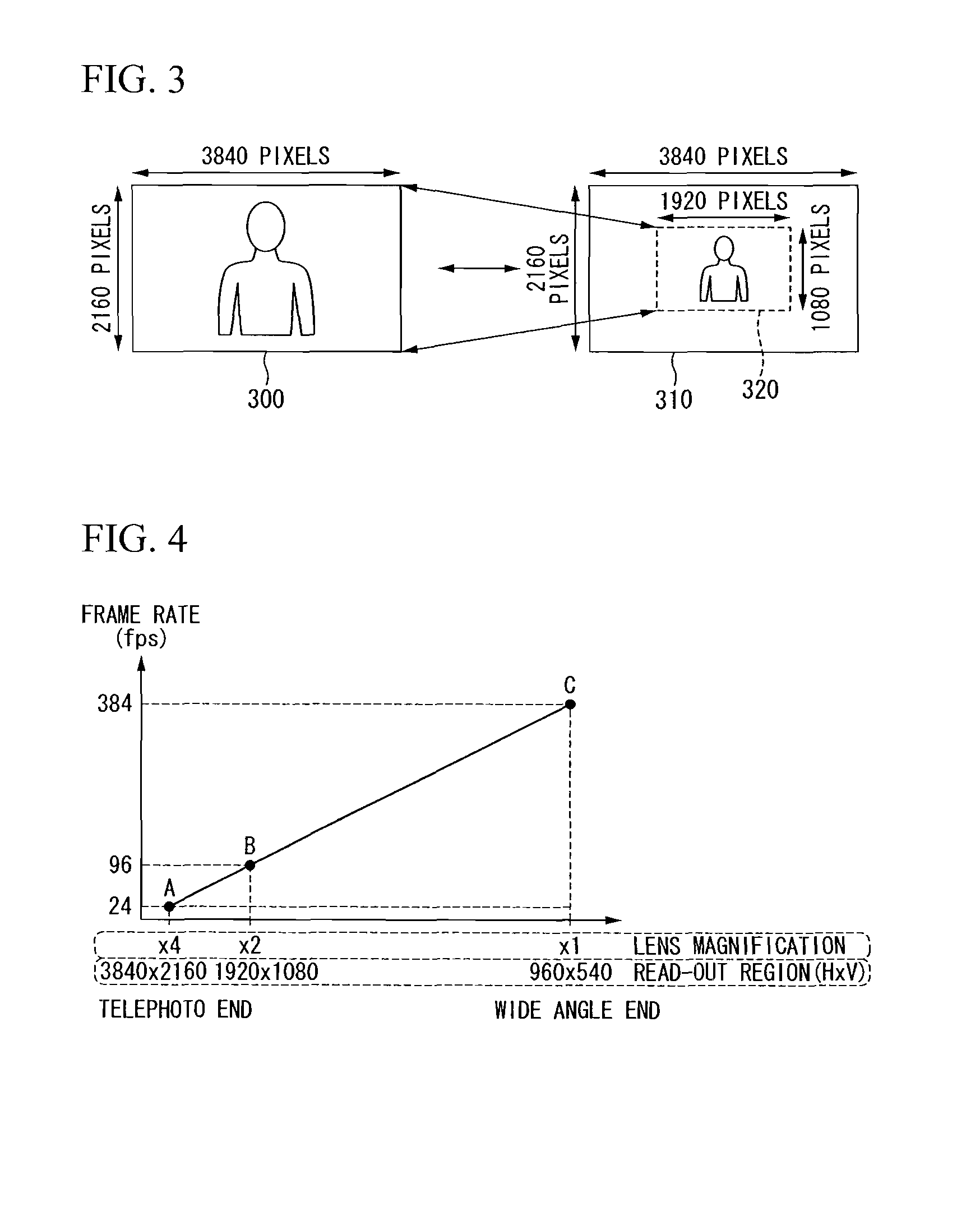
[0057]Next, the second embodiment of the present invention will be described. Although it is possible to apply the imaging apparatus in accordance with the first embodiment to an apparatus with interchangeable lenses, since there are effects due to individual differences of lenses such as magnification accuracy and image curvature due to aberration, even if the magnification of the lens 1 and the size of the read-out region are independently set so that the photographic angle of view is actually constant with respect to the size of the photographic subject, the size of the read-out region does not necessarily change in a linear manner corresponding to a linear change in the magnification of the lens 1. Therefore, in an imaging apparatus in accordance with the present embodiment, by recording the magnification of the lens 1 that includes the individual difference of the lens 1 and the size of the read-out region that corresponds thereto, even when various lenses are used, it is possi...


PUM


Abstract

The imaging apparatus of the present invention is provided with an image-forming lens that images light from a photographic subject; an imaging part that accumulates a pixel signal that corresponds to an optical image formed by the image-forming lens, reads the pixel signal and outputs the pixel signal as an imaging signal; a lens magnification control part that controls a magnification of the image-forming lens; a read-out region control part that controls the size of a read-out region of the pixel signal; and a frame rate control part that controls a frame rate of the imaging signal. In the imaging apparatus of the present invention, the magnification of the image-forming lens, the size of the read-out region, and the frame rate are controlled so that an angle of view of an image based on the imaging signal is constant.

Description

TECHNICAL FIELD[0001]The present invention relates to an imaging apparatus that is capable of changing the frame rate of an imaging signal.[0002]Priority is claimed on Japanese Patent Application Publication No. 2007-90468, filed Mar. 30, 2007, the content of which is incorporated herein by reference.BACKGROUND ART[0003]In conventional video production such as for television and movies, filming is performed that changes the number of frames that are imaged per second, that is, the frame rate, in order to impart a special effect to the video. For example, when imaging is performed by making the frame rate of the imaging signal faster than the frame rate of a playback signal, the video that is played back at the frame rate of the playback signal becomes a slow motion video. The faster the imaging frame rate becomes with respect to the playback frame rate, the playback video becomes a slower slow motion video, and the influence of the special effect becomes greater.[0004]Conventionally...

Claims


Application Information

Patent Timeline
Patent Type & Authority Applications(United States)
IPC IPC(8): H04N5/232G03B7/00H04N5/225H04N5/335H04N5/345H04N5/353H04N5/374H04N5/376
CPCG03B7/20H04N5/3454H04N5/23296H04N3/1562H04N23/69H04N25/443
Inventor HANEDA, KAZUHIRO
Owner OLYMPUS CORP
Why Eureka
Try Eureka