
Airbag apparatus

a technology of airbags and airbags, which is applied in the direction of vehicular safety arrangements, pedestrian/occupant safety arrangements, vehicle components, etc., can solve the problems of hardly steady timing of sewing thread rupture, inability to secure a predetermined volume of airbags, and failure to thoroughly open the communication hol

Active Publication Date: 2010-01-21
TOYODA GOSEI CO LTD
View PDF9 Cites 6 Cited by
  • Summary
  • Abstract
  • Description
  • Claims
  • Application Information

AI Technical Summary

Benefits of technology

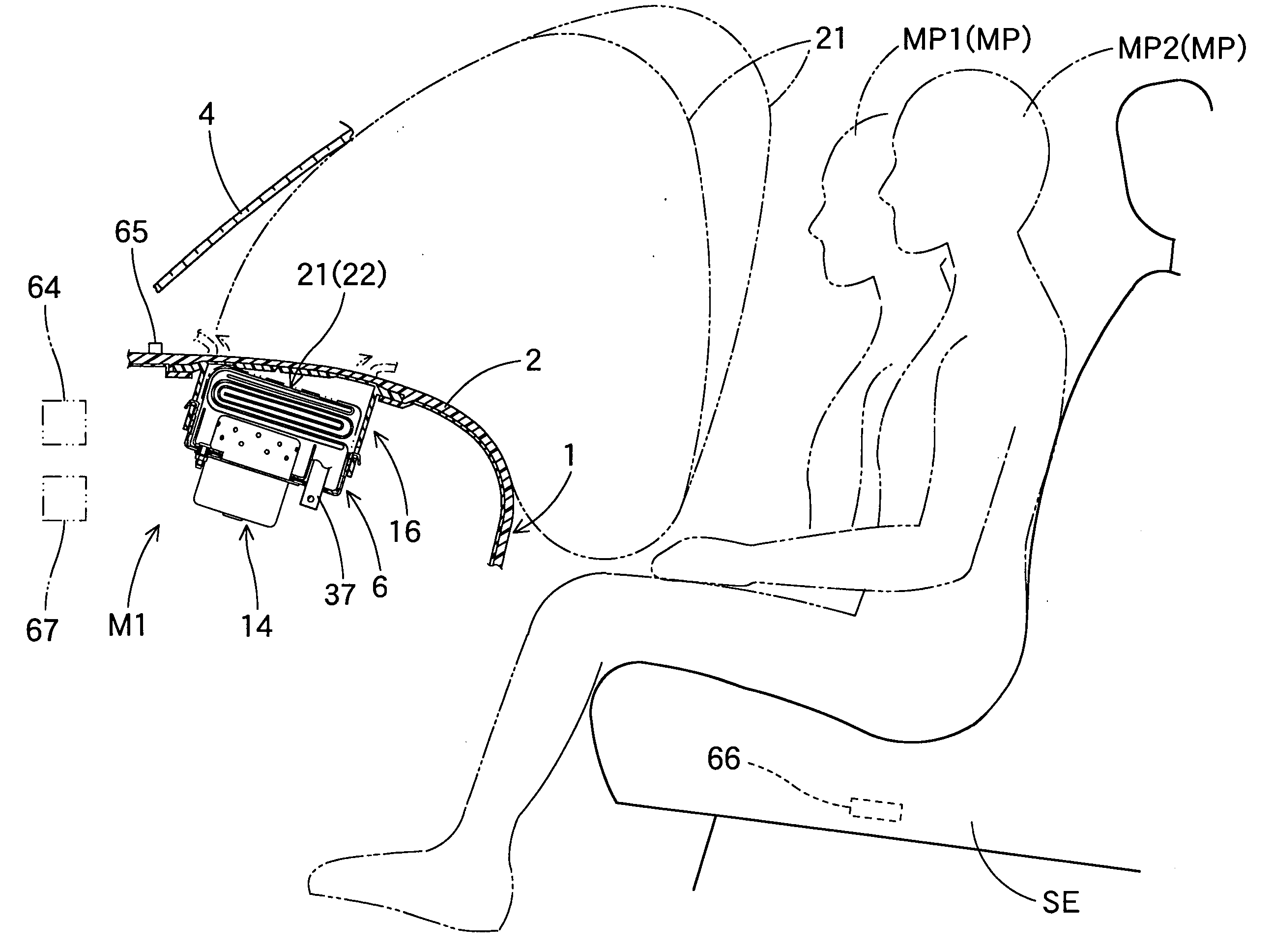
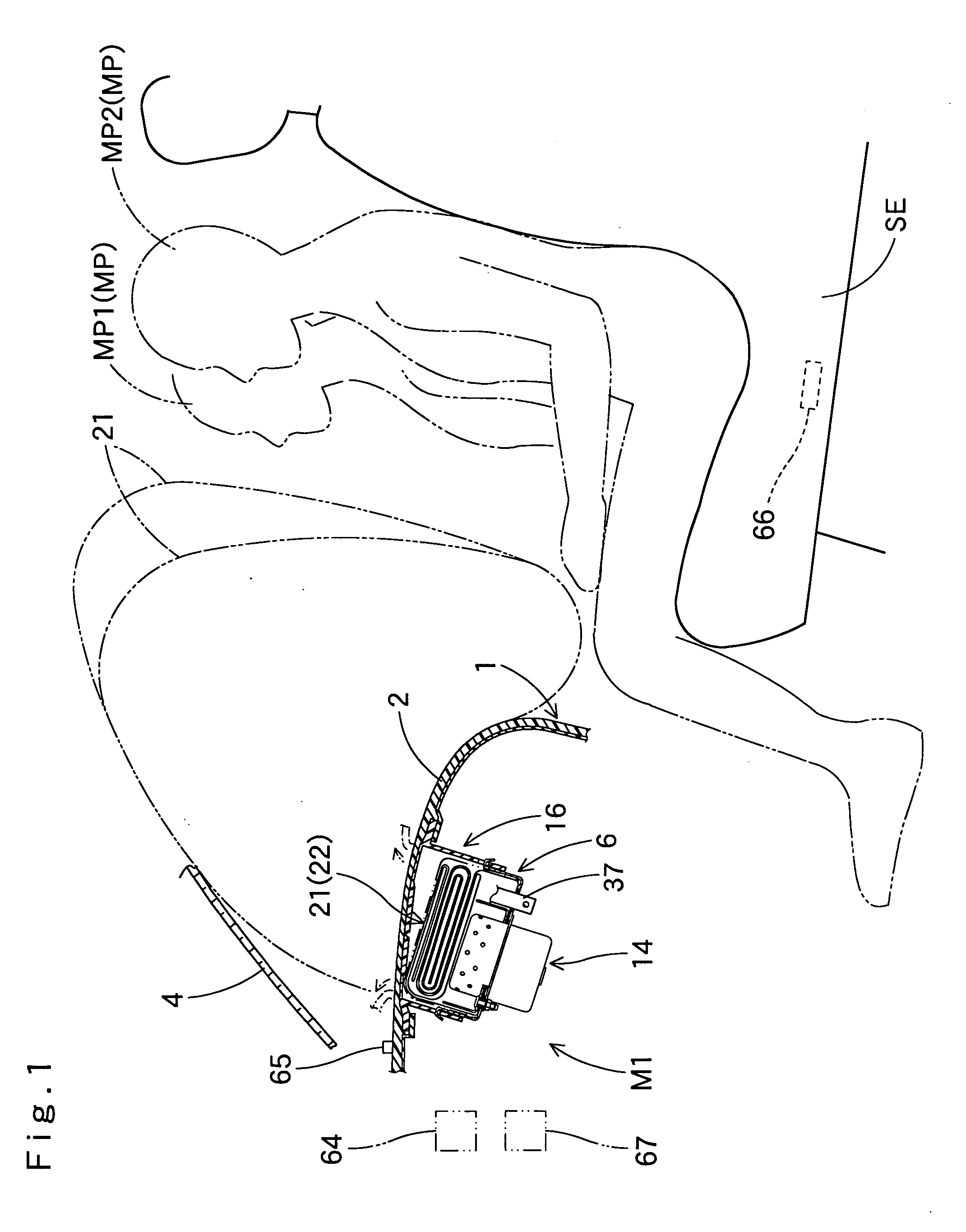
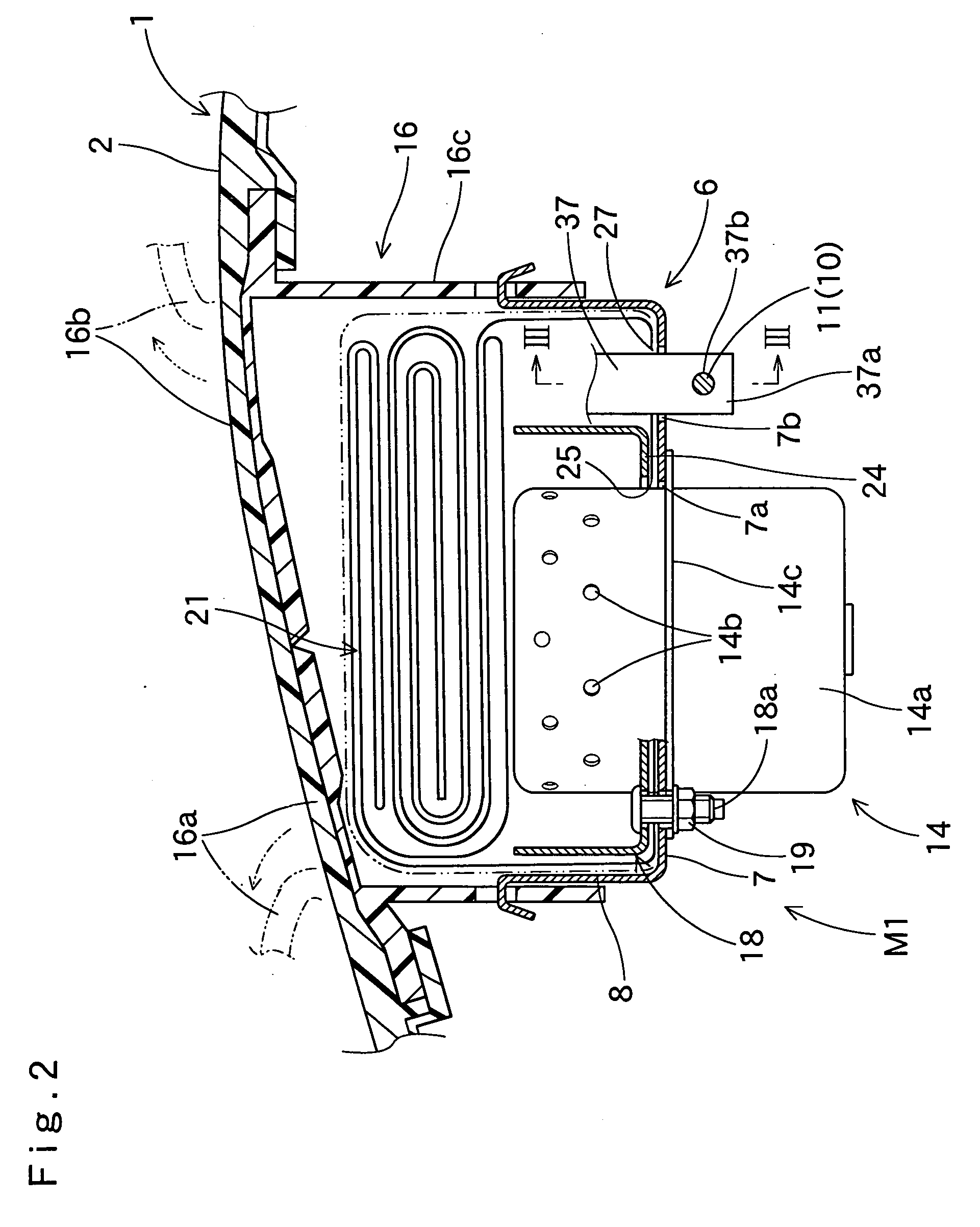
The present invention provides an airbag apparatus that can inflate quickly into a steady contour in each of inflation modes, even if the airbag is controlled by a control device that determines the desired inflation mode. The airbag includes a housing, an airbag and an anchor mechanism that regulates the operation of an open / close element. The open / close element can be a flexible sheet-like member or part of the bag body, and the connection between the open / close element and the anchor mechanism is releasable. The airbag can inflate in small-volume mode or big-volume mode depending on the needs of the passenger. The invention provides an airbag apparatus that can protect passengers from injury during a car accident.

Problems solved by technology

However, with the above configuration, there is a possibility that the sewing threads that sew the tether and circumferential wall of the inner bag fail to rupture thoroughly in big-volume mode and the airbag cannot secure a predetermined volume.
Moreover, the timing of rupture of the sewing threads is hardly steady.

Method used


Image

  • Airbag apparatus
  • Airbag apparatus
  • Airbag apparatus

Examples


first embodiment

[0068]In the airbag apparatus M1 of the first embodiment, the airbag 21 includes the bag body 22, the supplementary bag 39, the communication hole 34 that communicates the bag body 22 and supplementary bag 39, and the open / close element 35 that opens and closes the communication hole 34. If the leading end portion 37a of the connecting member 37 extending from the open / close element 35 is kept anchored by the anchor mechanism 10, the airbag 21 inflates with the communication hole 34 closed off by the open / close element 35, such that the supplementary bag 39 is not fed with inflation gas, i.e. the airbag 21 completes inflation in small-volume mode in which only the bag body 22 inflates, as shown in FIGS. 10 and 12. If the connecting element 37 is not anchored by the anchor mechanism 10, the communication hole 34 is allowed to open up and inflation gas G flows into the supplementary bag 39 such that the airbag 21 completes inflation in big-volume mode in which both the bag body 22 and...

second embodiment

[0085]In the airbag apparatus M2 of the second embodiment, too, the airbag 21A includes the bag body 22A, the supplementary bag 39A, the communication hole 70 that communicates the bag body 22A and supplementary bag 39A, and the flap member 72, acting as the open / close element, that opens and closes the communication hole 70. The opening of the communication hole 70 and inflation of the supplementary bag 39A are triggered only by disconnecting the connecting element 73 extending from the flap member 72 and anchor mechanism 10, and therefore, the timing of opening of the communication hole 70 is steady. Furthermore, the opening of the communication hole 70 assures the inflation of entire supplementary bag 39A. Accordingly, the contour of the airbag 21A is steady at full inflation in big-volume mode.

[0086]Therefore, in the airbag apparatus M2 of the second embodiment, too, the airbag 21A is inflatable quickly into a steady contour in each of inflation modes although controlled by a co...


PUM


Abstract

An airbag of an airbag apparatus includes a bag body, a supplementary bag, a communication hole that communicates the bag body and the supplementary bag, an open / close element that opens and closes the communication hole and a connecting element extending from the open / close element. The connecting element is connected at the leading end to an anchor mechanism that regulates the operation of the open / close element under control of a control device. The open / close element keeps closing the communication hole while the anchor mechanism holds the connecting element whereas opens the communication hole when the anchor mechanism releases the connecting element such that inflation gas is fed into the supplementary bag.

Description

[0001]The present application claims priority from Japanese Patent Application No. 2008-185408 of Bito et al., filed on Jul. 16, 2008, the disclosure of which is hereby incorporated into the present application by reference.BACKGROUND OF THE INVENTION[0002]1. Field of the Invention[0003]The present invention relates to an airbag apparatus that includes an airbag inflatable in a suitable inflation mode under control of a control device.[0004]2. Description of Related Art[0005]JP11-321506A discloses an airbag apparatus wherein the contour of the airbag at full inflation is controllable by a control device. This airbag apparatus includes a dual output inflator and an airbag that includes a bag body, an inner bag disposed inside the bag body and a tether that connects the bag body and inner bag while determining a clearance between the inner bag and bag body. The tether is sewn to part of the circumferential wall of the inner bag so as to reduce the volume of the airbag. The inflator in...

Claims


Application Information

Patent Timeline
Patent Type & Authority Applications(United States)
IPC IPC(8): B60R21/16
CPCB60R21/233B60R21/2338B60R2021/23384B60R2021/0004B60R2021/23324B60R21/239
Inventor ADACHI, YUICHIBITO, KAZUAKI
Owner TOYODA GOSEI CO LTD
Learn More