

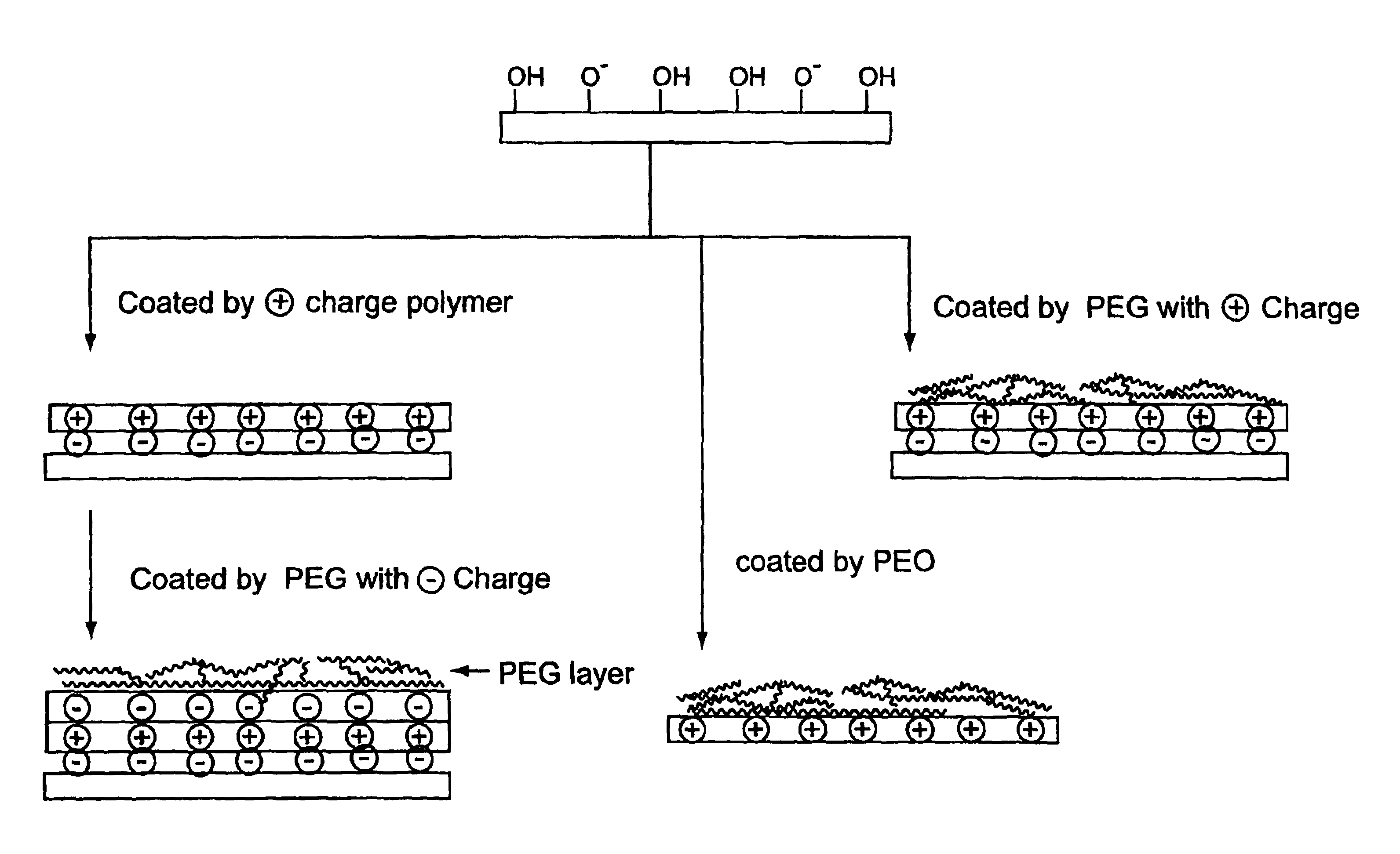
Surface coating for microfluidic devices that incorporate a biopolymer resistant moiety
a technology of biopolymer resistance and microfluidic devices, which is applied in the direction of fluid pressure measurement, liquid/fluent solid measurement, peptide measurement, etc., can solve the problems of loss of separation efficiency, peak tailing, and particularly problematic charging surfaces of capillaries and channels of separation devices, and achieve stable and reproducible electroosmotic flow, and suppress biopolymer adsorption
- Summary
- Abstract
- Description
- Claims
- Application Information
AI Technical Summary
Benefits of technology
Problems solved by technology
Method used
Image

Examples
example 1
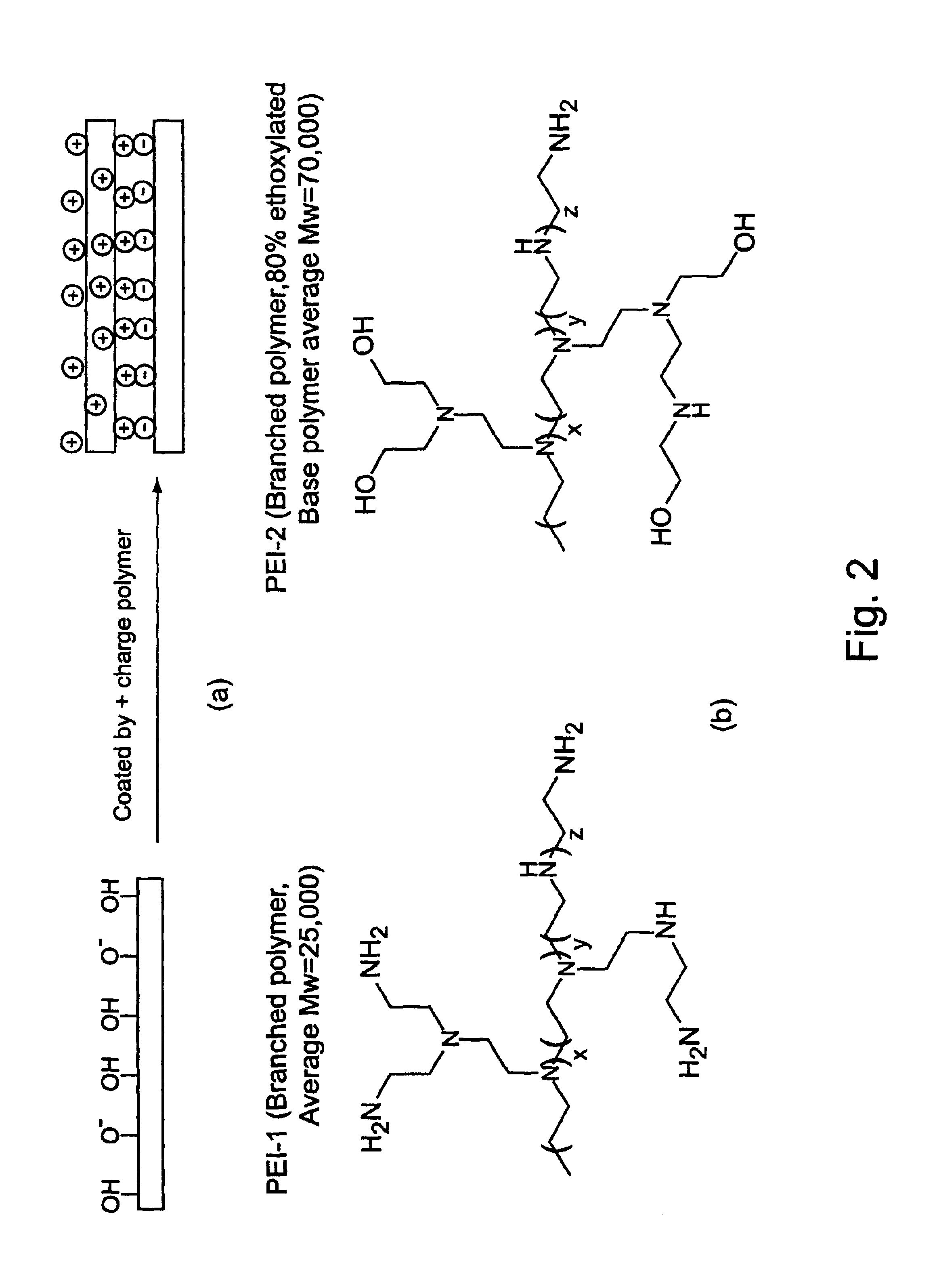
Example 1 provides a comparison of biopolymer adsorption in devices coated with PEI-1 and PEI-2. PEI-1 is a branched polyethyleneimine with average MW=25,000. PEI-2 is also a branched polyethyleneimine with a base polymer MW=70,000 and has 80% of the amino groups ethoxylated. Both polymers were used to coat microfluidic devices to generate stable, reversed electroosmotic flow. The PEI-2 coating was found to exhibit less protein adsorption than the PEI-1 coating, as judged by comparing electroosmotic flow measurements and PTP1b enzyme assay results for the coated devices.
1.1 Materials and Methods
1.1a PEI Coated Devices
The microfluidic devices used for enzyme assays measuring electroosmotic mobility (EO), had the channel format shown FIGS. 9(a) and 9(b) (with 20 μm deep channels). The top surfaces of new devices were treated with Repel-Silane-ES. The microchannels were cleaned prior to coating by successive rinses with 1N NaOH, water, 1N HCl, water and ethanol, and then dried overnigh...
example 2
A PTP1B assay using Caliper's microfluidic device is illustrated in Example 2. The microfluidic device surface has been modified with a physically adsorbed high-molecular-mass polyethyleneimine coating. The coating provides a stable, reversed electroosmotic flow surface. Devices coated with 80% ethoxylated polyethyleneimine (PEI-2) exhibited good electroosmotic flow (reversed direction), and show much less protein adsorption for both positively and negatively charged proteins than uncoated glass devices. In uncoated glass devices, the assay is typically run with added sulfobetaine (NDSB) to prevent the adsorption of the enzyme to the walls of the microchannel. Thus, as an additional test of PEI-2 coated devices, the PTP1B assay was run using buffers which did not contain NDSB.
2.1. Materials and Methods
2.1a PEI-2 Coated Devices
The devices used for this assay had a channel format as shown in FIGS. 9(a) and 9(b) (20 μm depth). The channel surfaces of each new device's surface was treat...
example 3
Example 3 further illustrates the resistance to protein adsorption imparted to microfluidic devices by coating these devices with poly(ethyleneimine) moieties. The adsorption of BSA and avidin was assayed.
3.1 Materials and Methods
3.1a PEI-2 Coated Device
The microfluidic devices used for enzyme assays measuring electroosmotic mobility (EO), had the channel format shown in FIG. 28 (15 micron channel depth). The top surfaces of new devices were treated with Repel-Silane-ES. The microchannels were cleaned prior to coating by successive rinses with 1N NaOH, water, 1N HCl, water and ethanol, and then dried overnight at 100-120° C. The devices were coated by filling the microchannels with the coating solution (8% PEI-2 / water) and left overnight, followed by extensive rinsing with water. The devices were stored dry after coating. The devices were conditioned by running assay buffer through the device for 10 minutes before starting the assay, and were rinsed extensively with water after runn...
PUM
 Abstract
Description
Claims
Application Information