Resonant switching power converter with burst mode transition shaping

a technology of switching power converter and burst mode, which is applied in the direction of electric variable regulation, process and machine control, instruments, etc., can solve the problems of non-uniform duration and/or spacing of pulses, and achieve the effects of reducing component stress, reducing audible vibration, and improving efficiency

Active Publication Date: 2010-01-28
CIRRUS LOGIC INC
View PDF99 Cites 18 Cited by
  • Summary
  • Abstract
  • Description
  • Claims
  • Application Information

AI Technical Summary

Benefits of technology

[0009]The above stated objectives of providing a low-power operating mode for a resonant switching power converter having reduced audible vibration, reduced component stresses and improved efficiency is achieved in a resonant switching power converter and its method of operation.
[0010]The resonant switching power converter includes a resonant tank circuit, a switching circuit for transferring energy to the resonant tank circuit from an input voltage source, and a transformer for coupling the resonant tank circuit to an output of the switching power converter. In a low-power mode of operation, the switching circuit issues burst of pulses having non-uniform duration and / or spacing to reduce the amplitude of a beginning and / or ending transient caused by the bursts. The last pulse of the burst may have a shorter duration than the pulses in the middle of the burst, which terminates the burst substantially near the point at which inductor current has reached a zero level. The first pulse of the burst may also be shortened in duration, to avoid overshoot in the amplitude of the oscillation at the beginning of the burst. Alternatively, the spacing between the initial and / or terminal pulses of the bursts may differ from the spacing of the pulses in the middle of the bursts to cause a reduction in the transient(s).
[0011]A number of pulses at the beginning of the burst and at the end of the burst may have durations set to a predetermined pattern of pulse-widths that gradually increase at the beginning of the burst and gradually decrease at the end of the bursts, to further reduce transient current levels, stress and audible vibration due to starting and stopping resonant operation. The voltage left on the output of the switching circuit at the end of the burst may be coordinated in polarity with the pulse polarity at the beginning of the next burst, to reduce the magnitude of the voltage step occurring at the output of the switching circuit at the beginning of the first pulse of the burst. The switching circuit may further enforce that the bursts always contain an even total of complete half-cycles, so that asymmetry within each burst and between bursts is prevented.

Problems solved by technology

In a low-power mode of operation, the switching circuit issues burst of pulses having non-uniform duration and / or spacing to reduce the amplitude of a beginning and / or ending transient caused by the bursts.

Method used


Image

  • Resonant switching power converter with burst mode transition shaping
  • Resonant switching power converter with burst mode transition shaping
  • Resonant switching power converter with burst mode transition shaping

Examples


Embodiment Construction

[0018]The present invention encompasses circuits and methods for reducing stress on components and audible vibration in output transformers of resonant switching power converters operating in low power burst mode. The efficiency in low power burst mode is also raised, due to the reduction of burst start and stop transient conditions that otherwise waste energy.

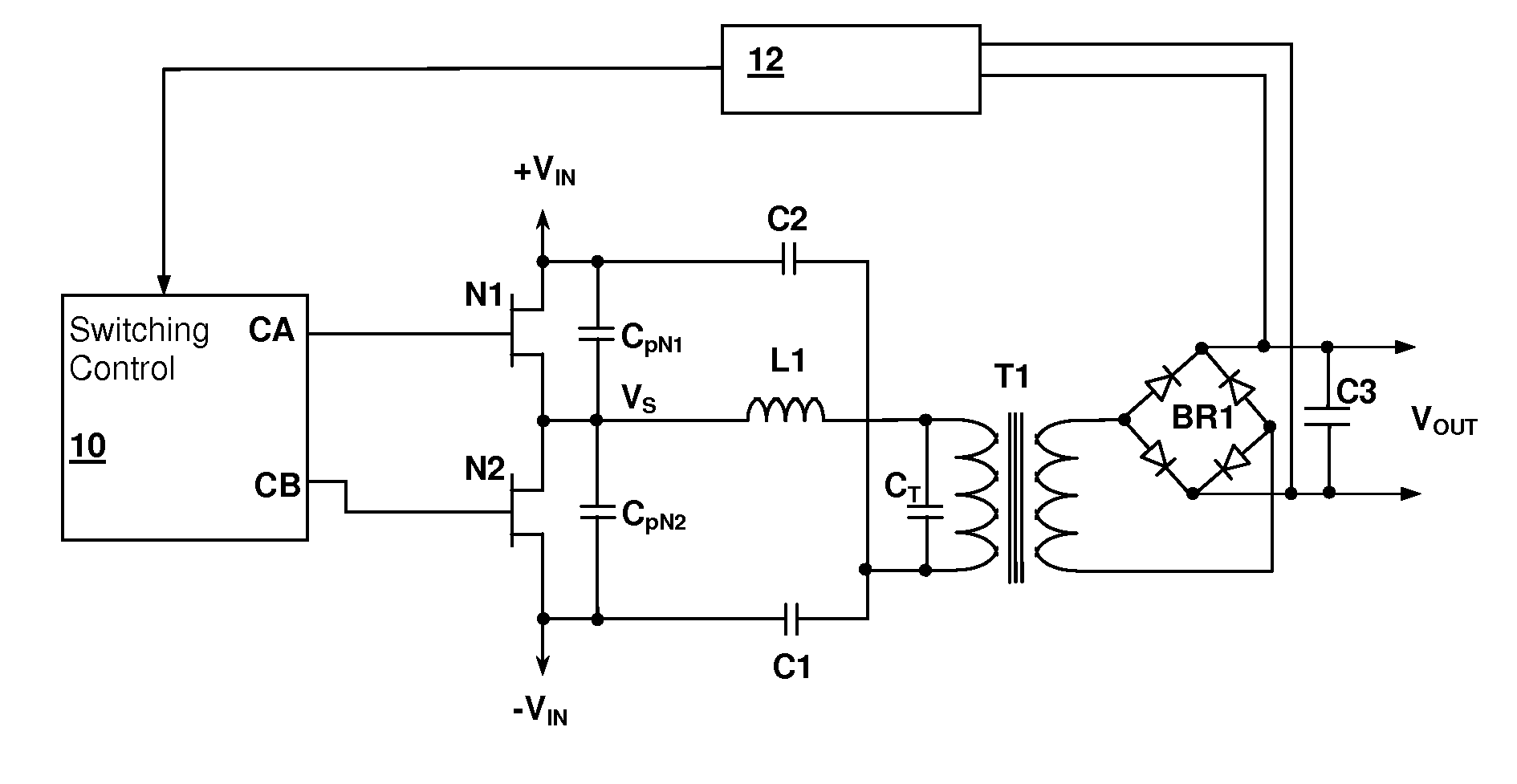
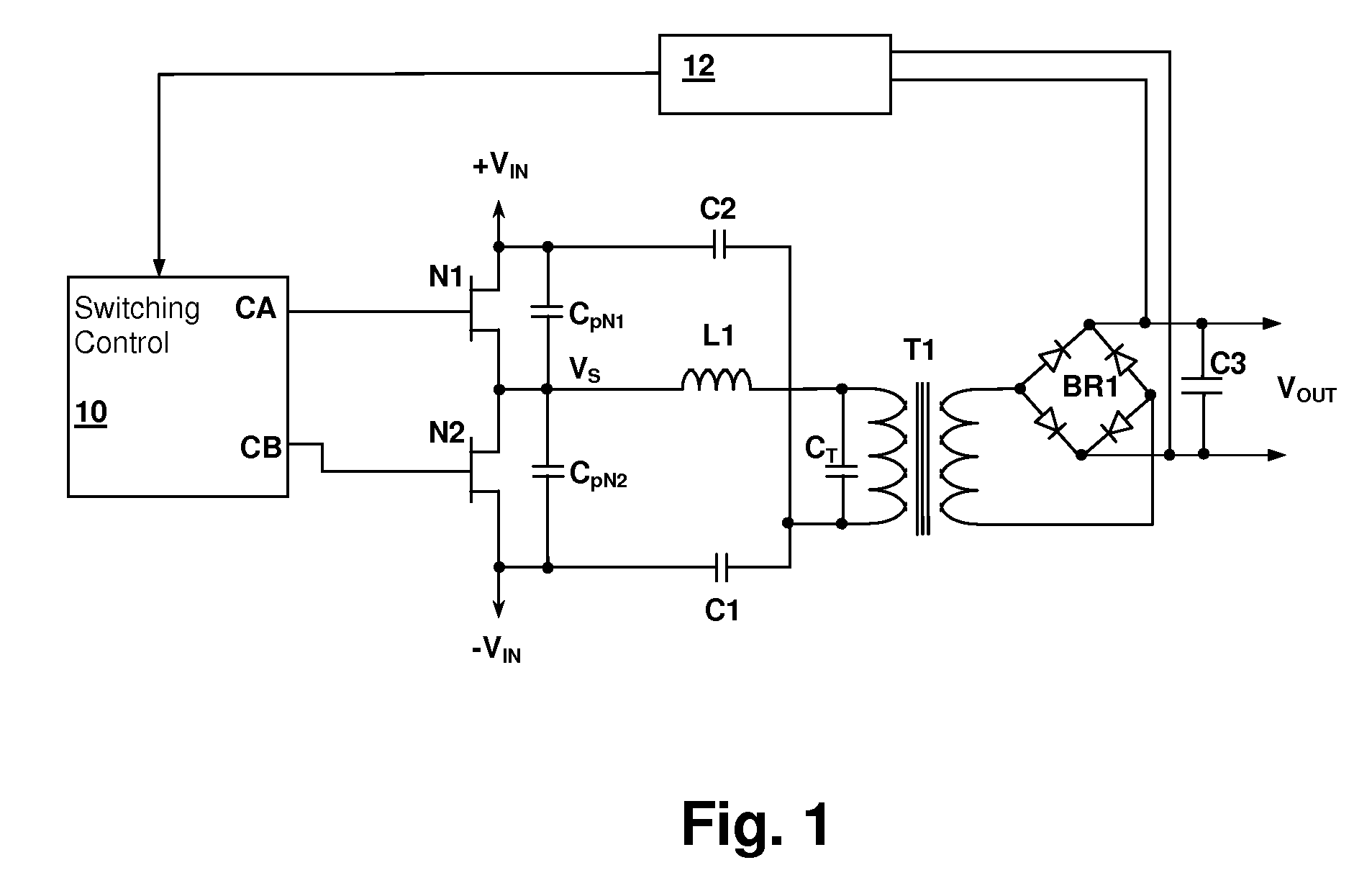
[0019]Referring now to FIG. 1, a resonant switching power converter circuit in accordance with an embodiment of the present invention is shown. A switching control circuit 10 controls a switching circuit implemented by transistors N1 and N2. A series-resonant tank circuit formed by an inductance and a capacitance and is energized by the switching action of transistors N1 and N2. A transformer T1 couples energy from the resonance tank circuit to a rectifier bridge BR1 which provides rectified current for charging output capacitor C3. Output voltage VOUT may be maintained at a predetermined voltage during burst mode by a feedbac...


PUM


Abstract

A resonant switching power converter having burst mode transitioning operates during low or zero load conditions with reduced audible noise and component stresses, while improving efficiency. Pulse bursts are generated with a beginning and/or ending pulse duration that differs from mid-burst pulse durations, in order to reduce an amplitude of transients otherwise generated at the beginning and/or end of the bursts. Alternatively, the spacing between the pulses at the beginning and/or end of the bursts may differ from the spacing between the pulses in the middle of the bursts to reduce the transient(s). A number of pulses at the beginning and/or end of the burst can also be set with gradually varying durations, to further reduce component stress and audible vibration in a transformer that couples the resonant tank to the output of the converter.

Description

[0001]This application Claims priority under 35 U.S.C. §119(e) to U.S. Provisional Patent Application Ser. No. 61 / 083,717 filed on Jul. 25, 2008.CROSS-REFERENCE TO RELATED APPLICATION[0002]The present U.S. patent application is related to U.S. patent application Ser. No. 12 / ______ entitled “AUDIBLE NOISE SUPPRESSION IN A RESONANT SWITCHING POWER CONVERTER”, filed contemporaneously herewith by the same inventor and assigned to the same Assignee. The disclosure of the above-referenced U.S. patent application is incorporated herein by reference.BACKGROUND OF THE INVENTION[0003]1. Field of the Invention[0004]The present invention relates generally to switching power regulator circuits, and more specifically, to a resonant switching power converter in which pulse durations at the start and end of a burst are reduced.[0005]2. Background of the Invention[0006]In resonant switching power converters, as output current demand falls, the switching frequency is raised to reduce the power output...

Claims


Application Information

Patent Timeline
Patent Type & Authority Applications(United States)
IPC IPC(8): H02M3/337
CPCH01F3/10H01F3/14H01F2038/026H01F38/08H01F38/02H02M1/42H02M1/0032Y02B70/10
Inventor MELANSON, JOHN L.GAETANO, MAURO L.
Owner CIRRUS LOGIC INC
Why Eureka
Try Eureka