Interior structure of vehicle equipped with curtain airbag

Inactive Publication Date: 2010-02-11
MAZDA MOTOR
View PDF24 Cites 13 Cited by
  • Summary
  • Abstract
  • Description
  • Claims
  • Application Information

AI Technical Summary

Benefits of technology

[0010]The present invention has been devises in view of the above-described concerns, and an object of the present invention is to provide an interior structure of a vehicle equipped

Problems solved by technology

Herein, however, fixing of the curtain member to the vehicle body is only conducted at the upper portion of the roof side rail portion, not at a pillar portion which is provided in fort or back of that, so a so-called “tension line” which should be formed so as to extend in the vehicle longitudinal direction by connecting a fixing point of the front end of the vehicle body (a front pillar) and a fixing point of the rear end of the vehicle body (a rear pillar) may not be formed properly.
If this tension line is not formed at the curtain member, there is a concern that the curtain member may not keep its inflating state properly covering the side window.
However, there is a concern that according to the structure of the airbag device in the above-described European publication the curta

Method used


Image

  • Interior structure of vehicle equipped with curtain airbag
  • Interior structure of vehicle equipped with curtain airbag
  • Interior structure of vehicle equipped with curtain airbag

Examples


Example

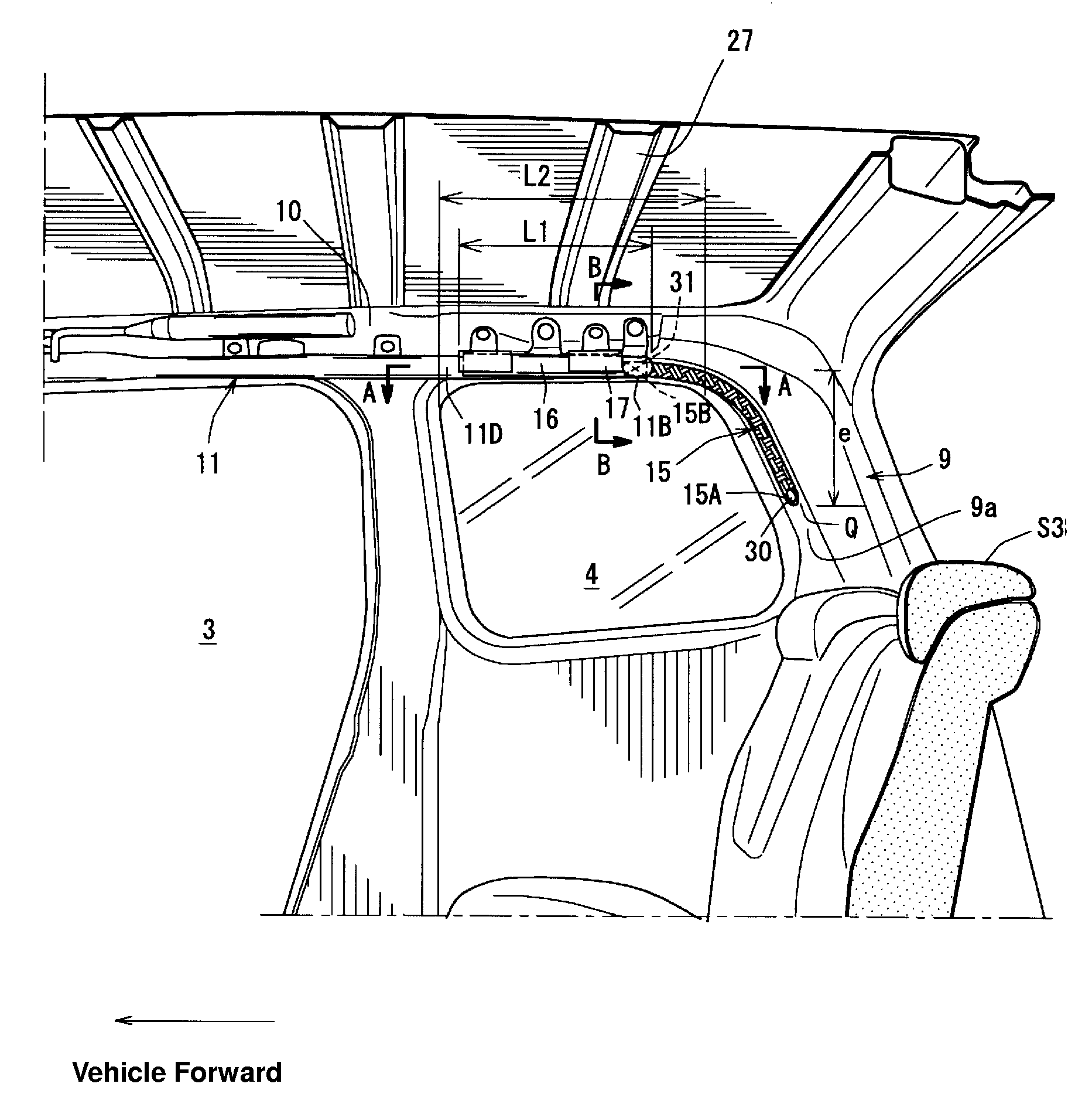
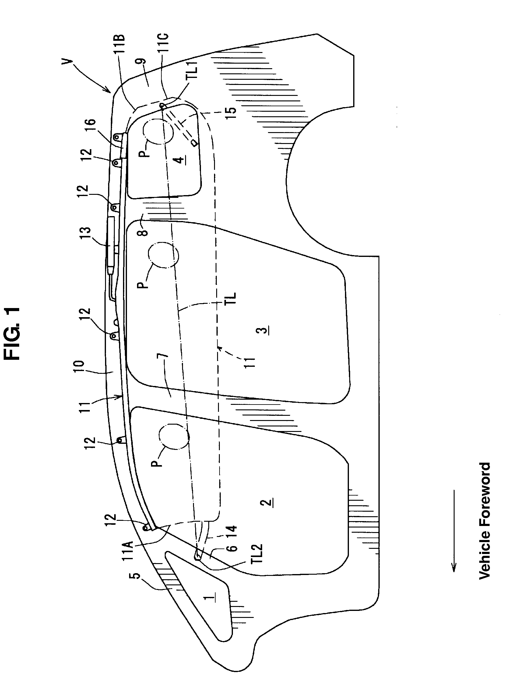
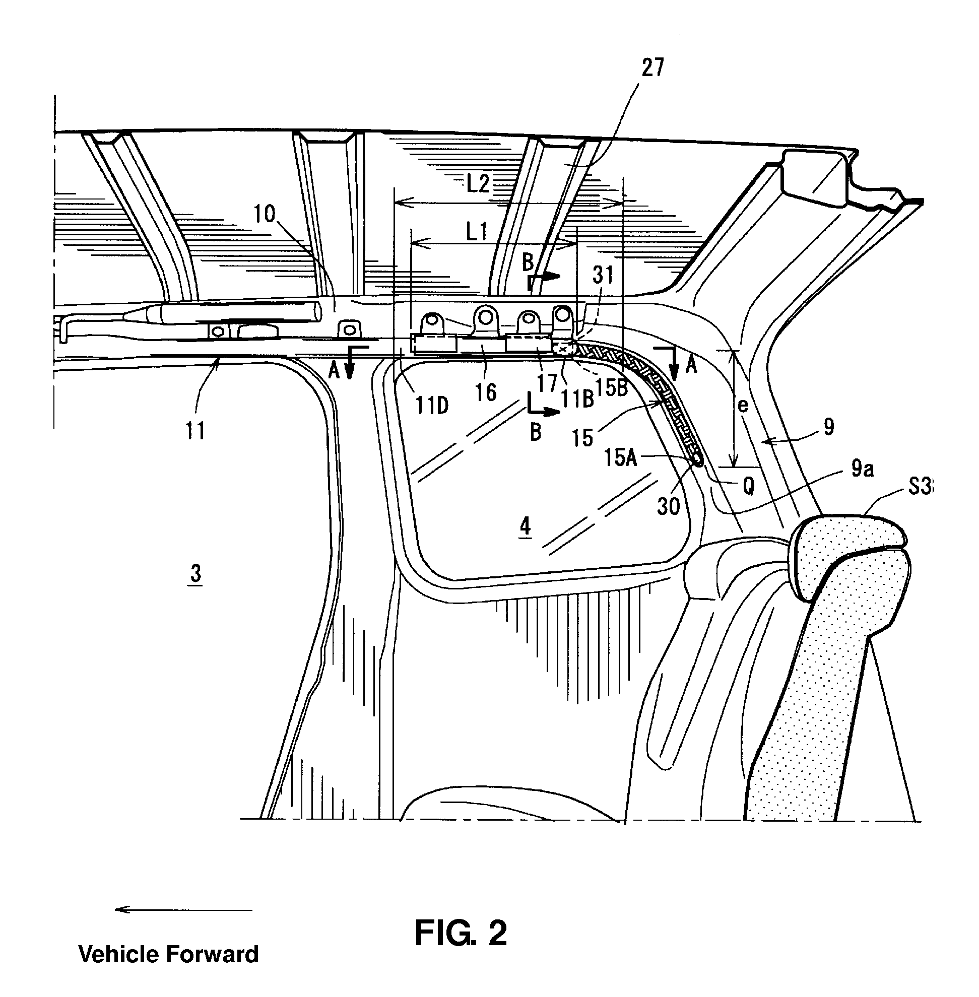
[0065]FIG. 1 is a schematic side view of an interior structure according to a first embodiment of the present invention. FIG. 2 is a side view of an inside of a vehicle compartment, in which a trim and the like beside a third-row seat are removed. FIG. 3 is a sectional view taken along line A-A of FIG. 2. FIG. 4 is a sectional view taken along line B-B of FIG. 2. As shown in FIG. 1, a vehicle V to which a first embodiment is applied is a wagon type of vehicle which is equipped with three rows of seats (not illustrated) so that three persons P (only heads are illustrated by one-dotted broken lines) can be seated in a vehicle compartment in a vehicle longitudinal direction. At a side wall of a vehicle body of the vehicle V are provided a triangular-window opening 1, a front-door opening 2, a rear-door opening 3, and a quarter-window opening 4 in order from the vehicle front.

[0066]Further, a first pillar 5 which extends obliquely rearward and upward is provided in front of the triangul...

Example

[0086]A second embodiment will be described referring to FIG. 7. FIG. 7 is a side view showing the inflation state of the curtain member according to the second embodiment. Herein, the same structure elements as those of the first embodiment are denoted by the same reference characters, and those detailed descriptions will be omitted.

[0087]According to the present invention, the fixing position of a second tether member 15′ to the fifth pillar 9 and the seam position of the second tether member 15′ to the curtain member 11 are positioned slightly above that (15 illustrated by the two-dotted broken line) of the first embodiment. Thereby, the second tether member 15′ can extend substantially horizontally when the curtain member 11 inflates. Specifically, a rear end 15′A of the second tether member 15′ is fixed to the substantially middle position of the fifth pillar 9 in the vertical direction, and a front end 15′B of the second tether member 15′ is seamed to the substantially middle ...

Example

[0092]A third embodiment will be described refereeing to FIGS. 8 through 13. According to the present embodiment, there is provided a connecting member which connects two separate specified portions of the curtain member. The same structure elements as those of the above-described first embodiment are denoted by the same reference characters, and those detailed descriptions will be omitted.

[0093]As shown in FIG. 10, a second tether member 115 of the third embodiment is configured such that its one end 115a is fixed to a free end 16a of the bending portion 16 via a first seam portion 115A and the other end 115b is fixed to a portion of the body portion 11D near the bend position 11E via a second seam portion 115B. Herein, as described above regarding the first embodiment, instead of the bending portion 16 which is formed to be turned back forward completely, another type of bending portion 116 may be applied in the present embodiment as well. In this case, a second tether member 115′...


PUM


Abstract

A second tether member is made of a long cloth member. Its rear end is fixed to a specified lower-side position of a fifth pillar which is located below the middle portion of this pillar in the vertical direction (i.e., at the position which is away from the top end of the fifth pillar by a distance of about 100 mm or greater) via a fixing pin. Its front end is fixed to a body portion of a curtain member via a seam portion. Accordingly, there can be provided the interior structure of a vehicle equipped with a curtain airbag which can properly form the tension line at the curtain member.

Description

BACKGROUND OF THE INVENTION[0001]The present invention relates to an interior structure of a vehicle equipped with a curtain airbag, and, in particular, relates to an interior structure of a vehicle equipped with a curtain airbag which is disposed inside a roof trim in a stored state.[0002]Conventionally, a curtain airbag device equipped with an airbag which inflates downward from the ceiling portion into the vehicle compartment in a curtain shape (hereinafter, referred to as a “curtain member”) at a vehicle side collision or rollover is known. This curtain airbag device is configured to reduce the collision impact at the vehicle side collision or to cover a side window for protection of passengers at the vehicle rollover.[0003]Japanese Patent Laid-Open Publication No. 2007-15536, for example, discloses the curtain airbag device in which the curtain member in the stored state is provided inside the roof trim at a roof side rail portion. According to this curtain airbag device, the v...

Claims


Application Information

Patent Timeline
IPC IPC(8): B60R21/21B60R21/213B60R21/232B60R21/2338
CPCB60R21/213B60R21/232B60R2021/23386B60R21/237B60R22/195B60R21/2338
Inventor YAMANISHI, MITSUTOSHIAMANO, FUMIO
Owner MAZDA MOTOR
Why Eureka
Try Eureka