Ultrasonic diagnostic apparatus, ultrasonic image display apparatus, and medical image diagnostic apparatus

a diagnostic apparatus and ultrasonic technology, applied in diagnostics, medical science, tomography, etc., can solve the problems of difficult to determine a position on an mpr image or a three-dimensional image, difficult to grasp a relative positional relationship between a plurality of images in such a case, and achieve the effect of rapid visual confirmation of a relative positional correspondence relationship

Active Publication Date: 2010-02-18
CANON MEDICAL SYST COPRPORATION
View PDF25 Cites 39 Cited by
  • Summary
  • Abstract
  • Description
  • Claims
  • Application Information

AI Technical Summary

Benefits of technology

[0009]In view of the above-described problem, it is an object of the present invention to provide an ultrasonic diagnostic apparatus, an ultrasonic image display apparatus, and a medical image diagnostic apparatus which can rapidly and easily v

Problems solved by technology

However, the technique for displaying an image concerning the tissue motion information using the conventional ultrasonic diagnostic apparatus has the following problem.
That is, in an MPR image, a polar map image, and a three-dimensional image, a positional correspondence relationship is difficult t

Method used


Image

  • Ultrasonic diagnostic apparatus, ultrasonic image display apparatus, and medical image diagnostic apparatus
  • Ultrasonic diagnostic apparatus, ultrasonic image display apparatus, and medical image diagnostic apparatus
  • Ultrasonic diagnostic apparatus, ultrasonic image display apparatus, and medical image diagnostic apparatus

Examples


first embodiment

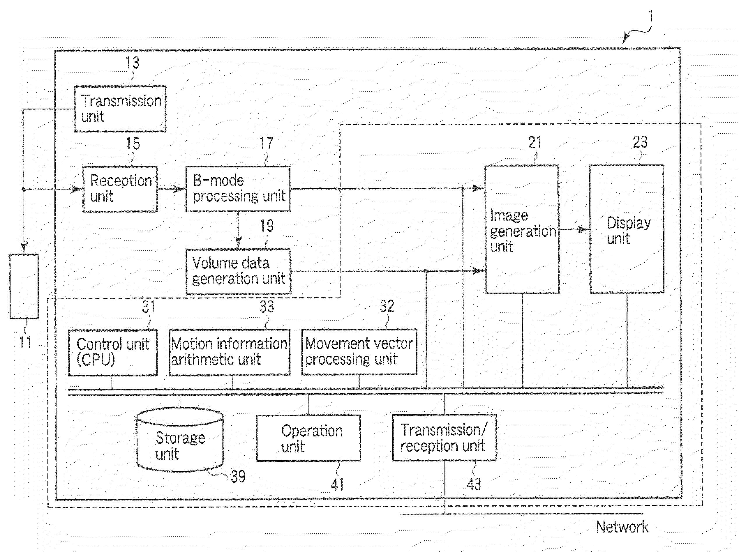
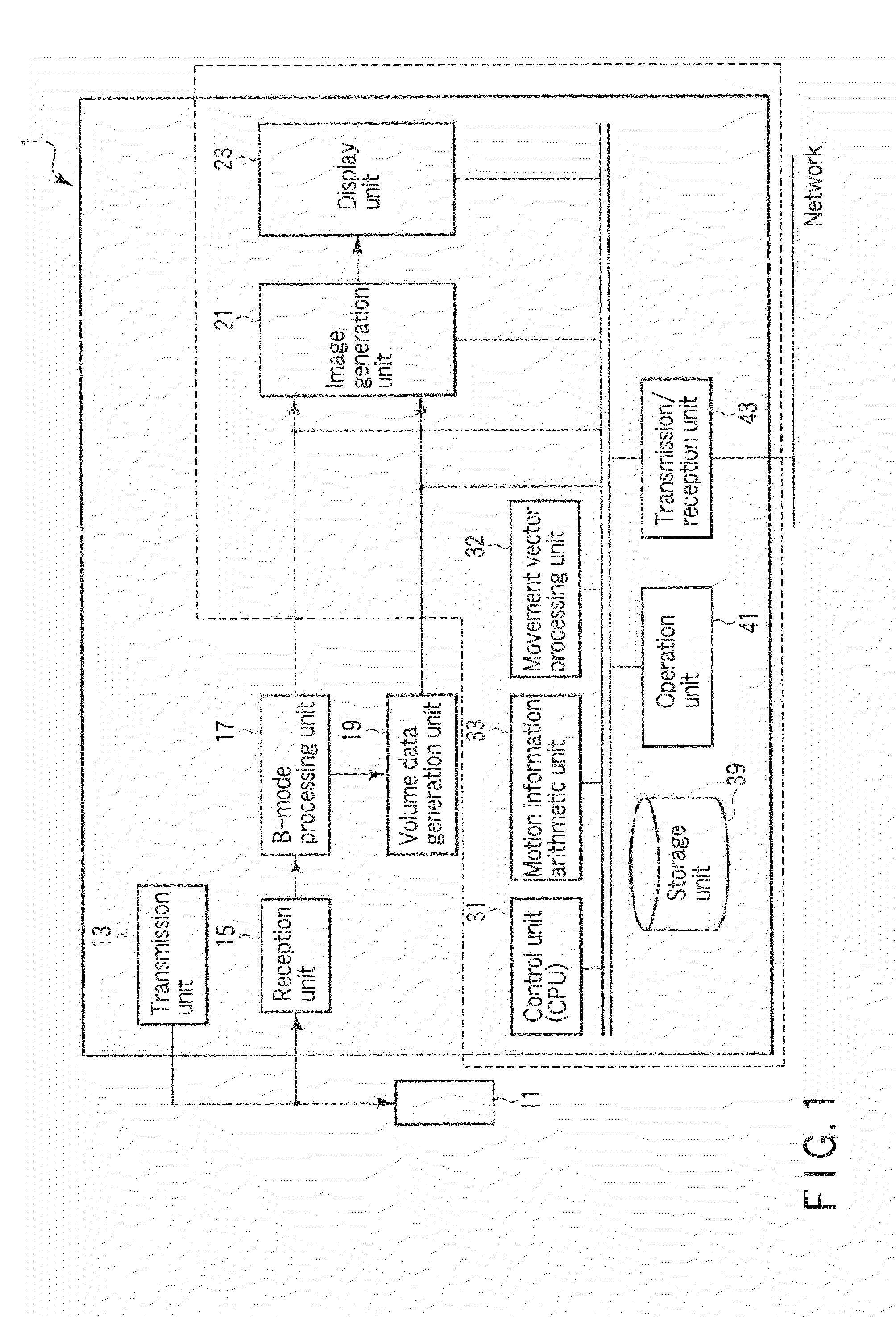
[0031]FIG. 1 is a block diagram of an ultrasonic diagnostic apparatus 1 according to the first embodiment. This ultrasonic diagnostic apparatus 10 includes an ultrasonic probe 11, a transmission unit 13, a reception unit 15, a B-mode processing unit 17, a volume data generation unit 19, an image generation unit 21, a display unit 23, a control unit (a CPU) 31, a movement vector processing unit 32, a motion information arithmetic unit 33, a storage unit 39, an operation unit 41, and a transmission / reception unit 43. It is to be noted that, when applying the present invention to an ultrasonic image display apparatus, the inside of a dotted line in FIG. 1 corresponds to constituent elements.

[0032]The ultrasonic probe 11 has a plurality of piezoelectric vibrators which generate ultrasonic waves based on a driving signal from the transmission unit 13 and convert reflected waves from a subject into electric signals, a matching layer provided to the piezoelectric vibrators, a backing mater...

modification 1

(Modification 1)

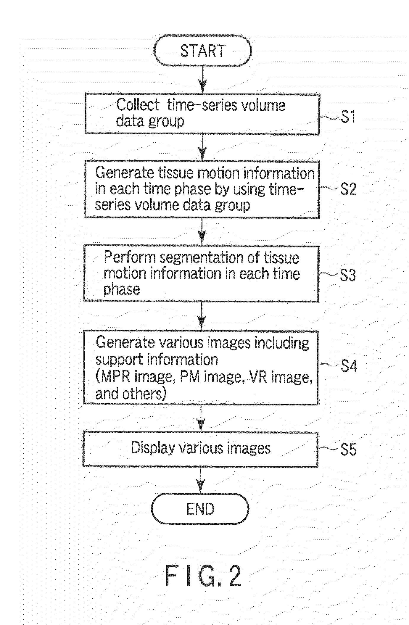
[0058]A modification of the ultrasonic diagnostic apparatus 1 according to this embodiment will now be explained. An ultrasonic diagnostic apparatus 1 according to this modification sets and displays a marker which indicates a desired local position as support information that is used to rapidly and easily visually confirm a relative positional correspondence relationship between each MPR image, a polar map image, and a three-dimensional image in a tissue motion information display function.

[0059]For example, a situation where a desired region in various images displayed at the step S5 is specified by an operator through an operation unit 41. In this case, a control unit 31 sets a position corresponding to the region specified by the operator on volume data in each time phase. An image generation unit 21 sets a marker indicating the region specified by the operator on each MPR image, a polar mapping image, and a three-dimensional image based on a judgment result. A d...

modification 2

(Modification 2)

[0062]Another modification of the ultrasonic diagnostic apparatus according to this embodiment will now be described. When the marker according to Modification 1 is set or changed on the polar mapping image or the three-dimensional image, a position corresponding to the set or changed marker is not present on the MPR image in some cases. An ultrasonic diagnostic apparatus according to this modification generates and displays an MPR image always including a position corresponding to the set or changed marker by automatically adjusting a position of an MPR cross section in such a case.

[0063]FIG. 5 is a flowchart showing a flow of a tissue motion information display processing according to this modification. In this drawing, for example, it is assumed that an operator specifies a desired marker set position with respect to a polar mapping image displayed at the step S5 through an operation unit 41. In this case, a control unit 31 sets a position corresponding to a regio...


PUM


Abstract

When displaying a plurality of images in different conformations in relation to information of a tissue motion typified by a heart wall motion, support information which is used to rapidly and easily visually confirm a relative positional correspondence relationship between an MPR image, a polar mapping image, and a three-dimensional image is generated and displayed. A marker indicative of a desired local position is set and displayed as required. Further, a position corresponding to the set or changed marker may not be present on the MPR image. In such a case, the MPR image always including a position corresponding to the set or changed marker is generated and displayed by automatically adjusting a position of an MPR cross section.

Description

CROSS-REFERENCE TO RELATED APPLICATIONS[0001]This application is based upon and claims the benefit of priority from prior Japanese Patent Application No. 2008-208633, filed Aug. 13, 2008, the entire contents of which are incorporated herein by reference.BACKGROUND OF THE INVENTION[0002]1. Field of the Invention[0003]The present invention relates to an ultrasonic diagnostic apparatus, an ultrasonic image display apparatus, and a medical image diagnostic apparatus that can generate and display an image concerning information of a tissue motion typified by a heart wall motion.[0004]2. Description of the Related Art[0005]In an ultrasonic diagnosis, how a heart beats or how a fetus moves can be displayed in real time by a simple operation, i.e., just applying an ultrasonic probe from a body surface, and examination can be repeatedly performed because of high safety. Besides, a scale of a system is smaller than that of any other diagnostic device using an X-ray, CT, or MRI, examination ca...

Claims


Application Information

Patent Timeline
IPC IPC(8): A61B8/14
CPCA61B6/503A61B8/08A61B8/483A61B8/0883A61B8/463A61B8/0858
Inventor OHUCHI, HIROYUKIABE, YASUHIKOKAWAGISHI, TETSUYAHASHIMOTO, SHINICHI
Owner CANON MEDICAL SYST COPRPORATION
Why Eureka
Try Eureka