Caliper brake device for vehicle
a brake device and vehicle technology, applied in the direction of brake wear compensation mechanism, mechanical equipment, transportation and packaging, etc., can solve the problems of frictional surface deformation, decreased frictional coefficient of the brake pad, and inability of the brake pad to exhibit its original braking for
- Summary
- Abstract
- Description
- Claims
- Application Information
AI Technical Summary
Benefits of technology
Problems solved by technology
Method used
Image
Examples
second embodiment
[0075]Referring to FIGS. 7 and 8, this invention will be described.
first embodiment
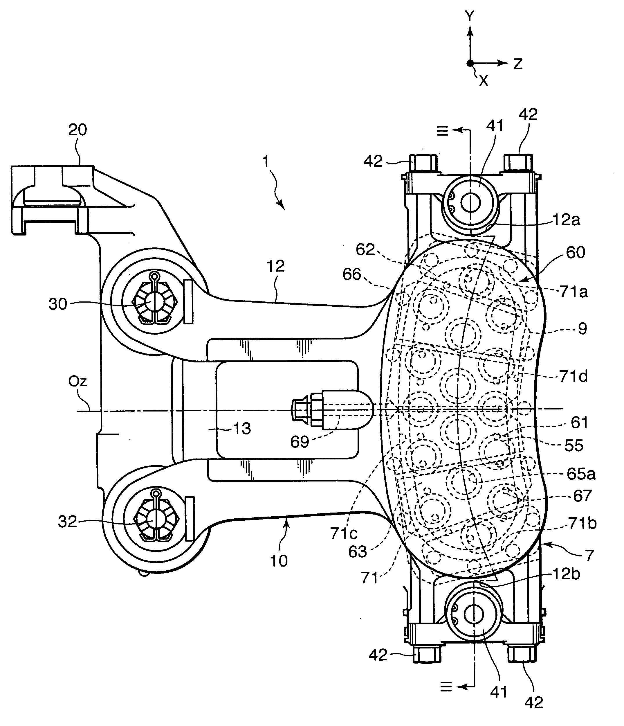
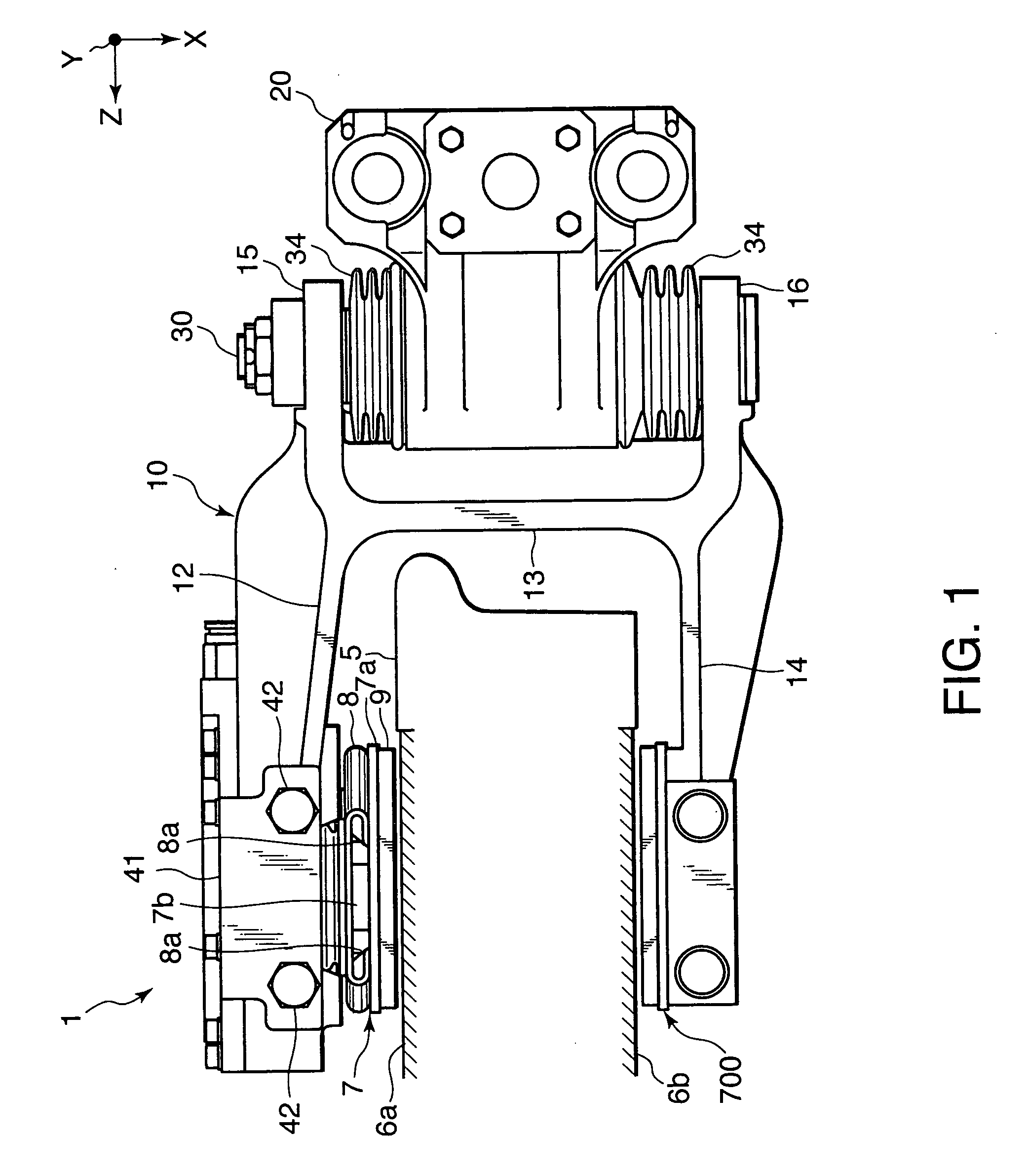
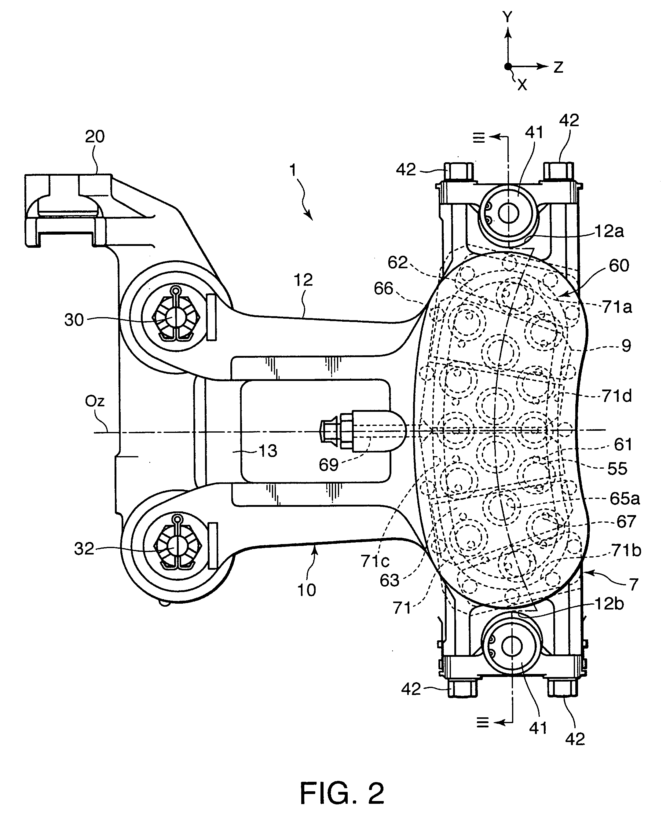
[0076]Referring to FIG. 8, the caliper brake device 1 according to this embodiment comprises a cylinder 80 formed in the first caliper arm 12 with two open ends, which takes the place of the cylinder 70 and a cover 92 that closes one end of the cylinder 80 to form a bottom portion. The diaphragm 75 is housed in the cylinder 80.
[0077]The cylinder 80 comprises a cylinder inner wall 82 that has a substantially elliptical cross-section and extends in the X axis direction, and a ring-shaped attachment seat 81 that is formed on a plane defined by the Y axis and the Z axis to latch the peripheral edge portion 76 of the diaphragm 75.
[0078]Referring to FIG. 7, the cylinder 80, the movable brake pad 7, the cover 92, and the attachment seat 81 are formed to be vertically symmetrical about the center line Oz of the brake caliper 10, which is parallel to the Z axis.
[0079]A plurality of bolt holes are formed in the attachment seat 81 at predetermined intervals, and the cover 92 is fixed to the a...
third embodiment
[0087]Referring to FIGS. 9 and 10, this invention will be described.
[0088]This embodiment is similar to the second embodiment, but the holder 8 is omitted and the movable brake pad 7 is supported by the respective anchor pins 43 directly.
[0089]The movable brake pad 7 is constituted by the lining 9, which is configured to contact the first frictional surface 6a, which is rotating, the body 7a to which the lining 9 is fixed, and the engaging portion 7b formed on the rear surface of the body 7a.
[0090]A ring-shaped engaging groove 86 is formed in the outer periphery of each anchor pin 43. Edges 85 that engage with the engaging grooves 86 in the upper and lower anchor pins 43 are formed respectively on the upper end and the lower end of the engaging portion 7b.
[0091]By engaging the edges 85 with the engaging grooves 86 in the upper and lower anchor pins 43, the movable brake pad 7 is latched to the first caliper arm 12. The anchor pins 43 are supported by the adjustors 41 to be capable...
PUM
 Abstract
Description
Claims
Application Information
 - R&D
- Intellectual Property
- Life Sciences
- Materials
- Tech Scout
- Unparalleled Data Quality
- Higher Quality Content
- 60% Fewer Hallucinations
Browse by: Latest US Patents, China's latest patents, Technical Efficacy Thesaurus, Application Domain, Technology Topic, Popular Technical Reports.
© 2025 PatSnap. All rights reserved.Legal|Privacy policy|Modern Slavery Act Transparency Statement|Sitemap|About US| Contact US: help@patsnap.com


