Electrode structure and battery device manufacturing method

Active Publication Date: 2010-02-25
TOYOTA JIDOSHA KK
View PDF22 Cites 62 Cited by
  • Summary
  • Abstract
  • Description
  • Claims
  • Application Information

AI Technical Summary

Benefits of technology

[0018]According to the electrode structure and the method of manufacturing the battery device of the present invention, temporary fixing is attained by an insulator and,

Problems solved by technology

When the bolt is inserted with pressure to the metal terminal for temporarily fixing the bolt on the metal terminal, th

Method used


Image

  • Electrode structure and battery device manufacturing method
  • Electrode structure and battery device manufacturing method
  • Electrode structure and battery device manufacturing method

Examples


embodiment 1

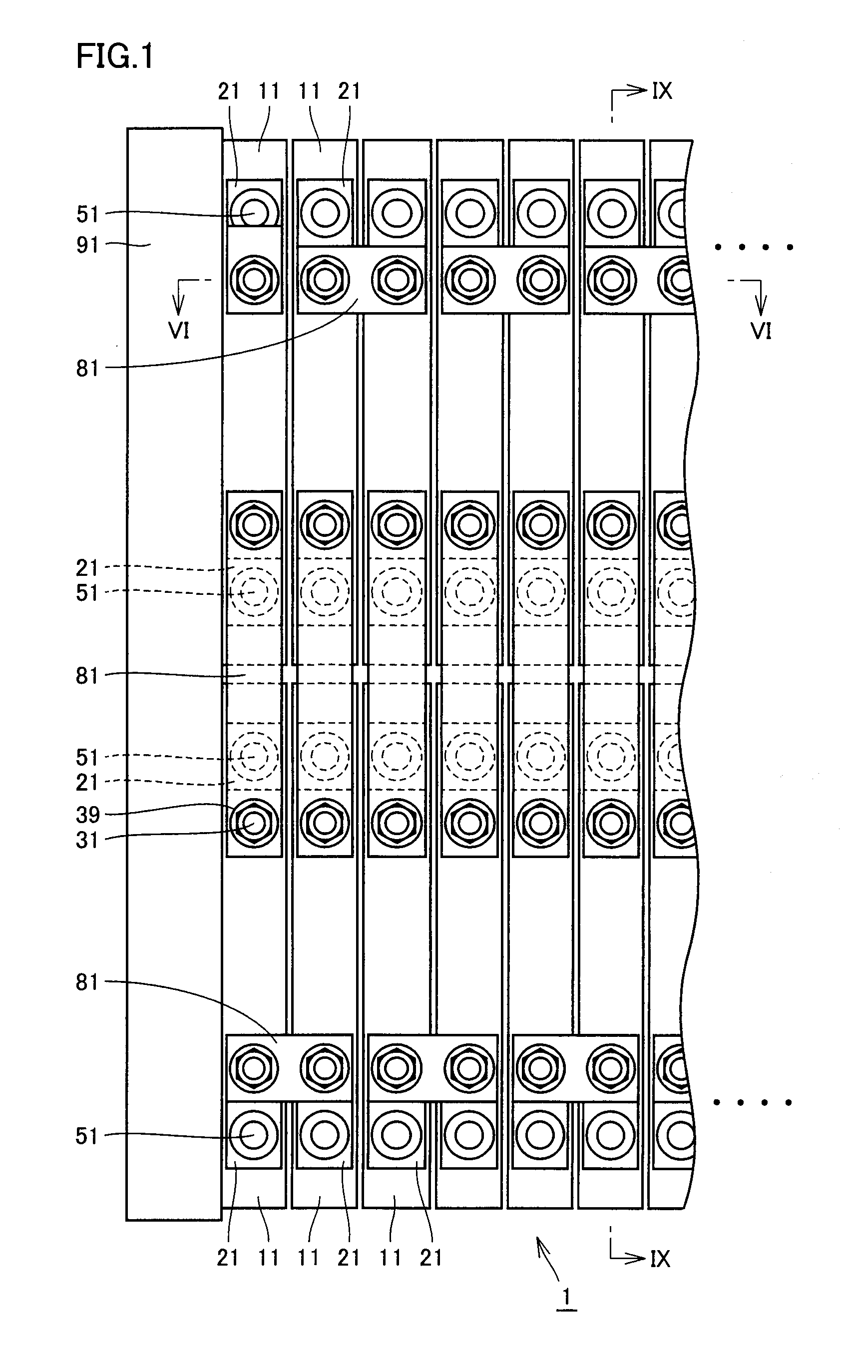
[0035]FIG. 1 is a plan view showing a structure of a battery device in accordance with the present embodiment. As shown in FIG. 1, a battery device 1 has a plurality of battery modules 11. In battery device 1 shown in FIG. 1, battery modules 11 are arranged in two rows with their main surfaces positioned parallel to each other. Though an example in which battery modules 11 are arranged in two rows is shown here, the modules may be arranged in one row or in three or more rows.

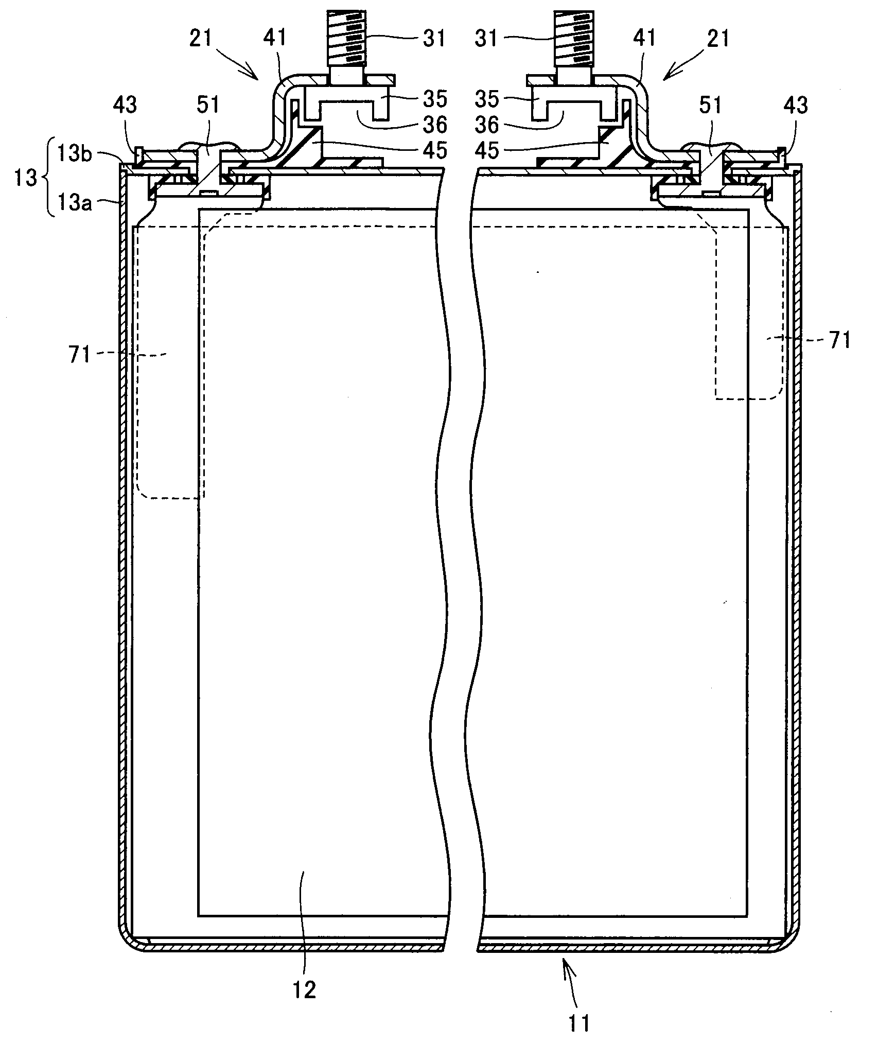
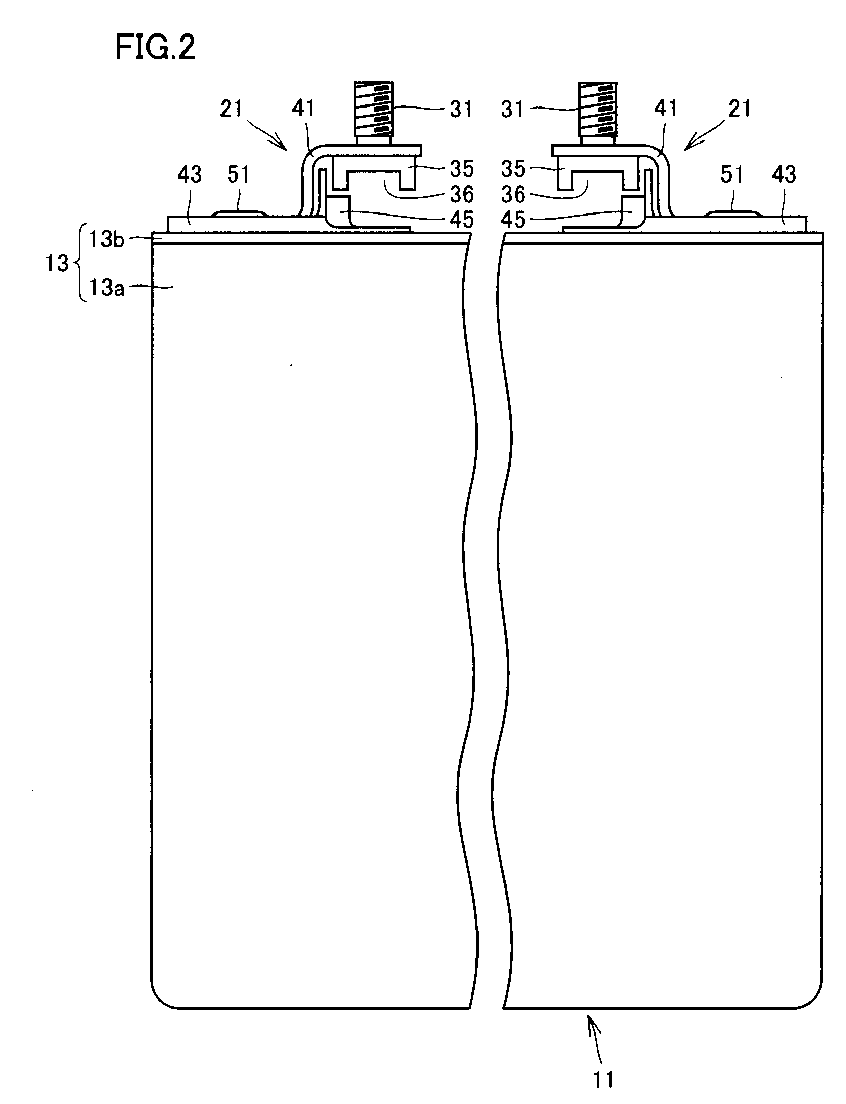
[0036]Each battery module 11 has electrodes 21 serving as positive and negative electrodes, respectively. Electrodes 21 of battery modules 11 arranged side by side are connected to each other by a bus bar 81. Bus bar 81 is formed of plate-shaped metal.

[0037]At an end portion of the thus arranged plurality of battery modules 11, a binding plate 91 is provided. Binding plates 91 apply a force in compressing direction, to the thus arranged plurality of battery modules 11 from opposite end portions. Consequently, ba...

embodiment 2

[0078]Next, Embodiment 2 will be described with reference to FIG. 11. FIG. 11 is a vertical sectional view showing a structure of an electrode, and it corresponds to FIG. 10 of Embodiment 1.

[0079]In the present embodiment, the structure of insulator 43 is changed such that insulator 43 serves to prevent dropping and co-rotation of bolt 31. Specifically, insulator 43 is formed to surround expanded section 35 of bolt 31, and expanded to fill the space between the lower side of bolt 31 and lid 13b, to form drop preventing section 45. Further, at a lower surface of insulator 43 and lower side of drop preventing section 45, an engaging projection 46 is formed, protruded downward.

[0080]Expanded section 35 of bolt 31 abuts on drop preventing section 45 and, therefore, dropping from metal terminal 41 is prevented. Further, as the expanded section 35 of bolt 31 is surrounded by wall portion 47 provided in drop preventing section 45, rotation of expanded section 35 is prevented by drop preven...

embodiment 3

[0083]Next, Embodiment 3 will be described with reference to FIGS. 12 and 13. FIG. 12 is a vertical sectional view showing a structure of an electrode, and it corresponds to FIG. 10 of Embodiment 1. FIG. 13 is a plan view of the battery module in accordance with the present embodiment. FIG. 13 shows a state before bus bar 81 is attached.

[0084]In the present embodiment, as in Embodiment 2, insulator 43 serves to prevent dropping and co-rotation of bolt 31. Further, in the present embodiment, stiffness reduced portion is formed at the bent portion of metal terminal 41.

[0085]In the present embodiment, expanded section 35 of bolt 31 is formed to have a hexagonal shape, and a flange 35a is provided on the screw-side end of expanded section 35. Flange 35a protrudes outward from the body of expanded section 35.

[0086]Drop preventing section 45 of insulator 43 is provided with a wall portion 47 that surrounds expanded section 35 of bolt 31. Wall portion 47 forms a hexagonal recess, to which ...


PUM

PropertyMeasurementUnit
Fractionaaaaaaaaaa
Thicknessaaaaaaaaaa
Widthaaaaaaaaaa

Abstract

An electrode is provided with a metal terminal extending from a battery module main body, a bolt which has an expanded section configuring a retaining section at a rear end portion and penetrates the metal terminal upward, and an insulating body which insulates the metal terminal and the battery module case one from the other. The insulating body is provided with a drop preventing section which abuts at least a lower surface of the expanded section of the bolt and prevents the bolt from dropping from the metal terminal.

Description

TECHNICAL FIELD[0001]The present invention relates to an electrode structure and a method of manufacturing a battery device and, more specifically, to an electrode structure for connecting a battery module to a bus bar and to a method of manufacturing a battery device to which the bus bar is connected.BACKGROUND ART[0002]A battery device mounted on a hybrid vehicle or an electric vehicle has a plurality of battery modules connected in series or in parallel. The plurality of battery modules are connected to each other by a bus bar. The battery module is provided with an electrode to be connected to the bus bar.[0003]For the connection to the bus bar, a bolt is attached to a metal terminal of the electrode. The bolt attached to the metal terminal penetrates through the bus bar, and screw-fixed in a nut, so that the bus bar is firmly fixed.[0004]Considering the process step of attaching the bus bar to the electrode, it is preferred to have the bolt temporarily fixed in advance on the m...

Claims


Application Information

Patent Timeline
IPC IPC(8): H01M2/02H01M50/50H01M50/505H01M50/522H01M50/562
CPCH01M2/202Y10T29/49108Y02E60/12H01M2/30Y02E60/10H01M50/50H01M50/522H01M50/562H01M50/505H01M50/543H01M50/20
Inventor TSUCHIYA, TAKENORINAGAI, HIROKIHIKOSAKA, MASAHIDE
Owner TOYOTA JIDOSHA KK
Why Eureka
Try Eureka