Discharge lamp lighting device, headlight device and vehicle having the same
- Summary
- Abstract
- Description
- Claims
- Application Information
AI Technical Summary
Benefits of technology
Problems solved by technology
Method used
Image
Examples
first embodiment
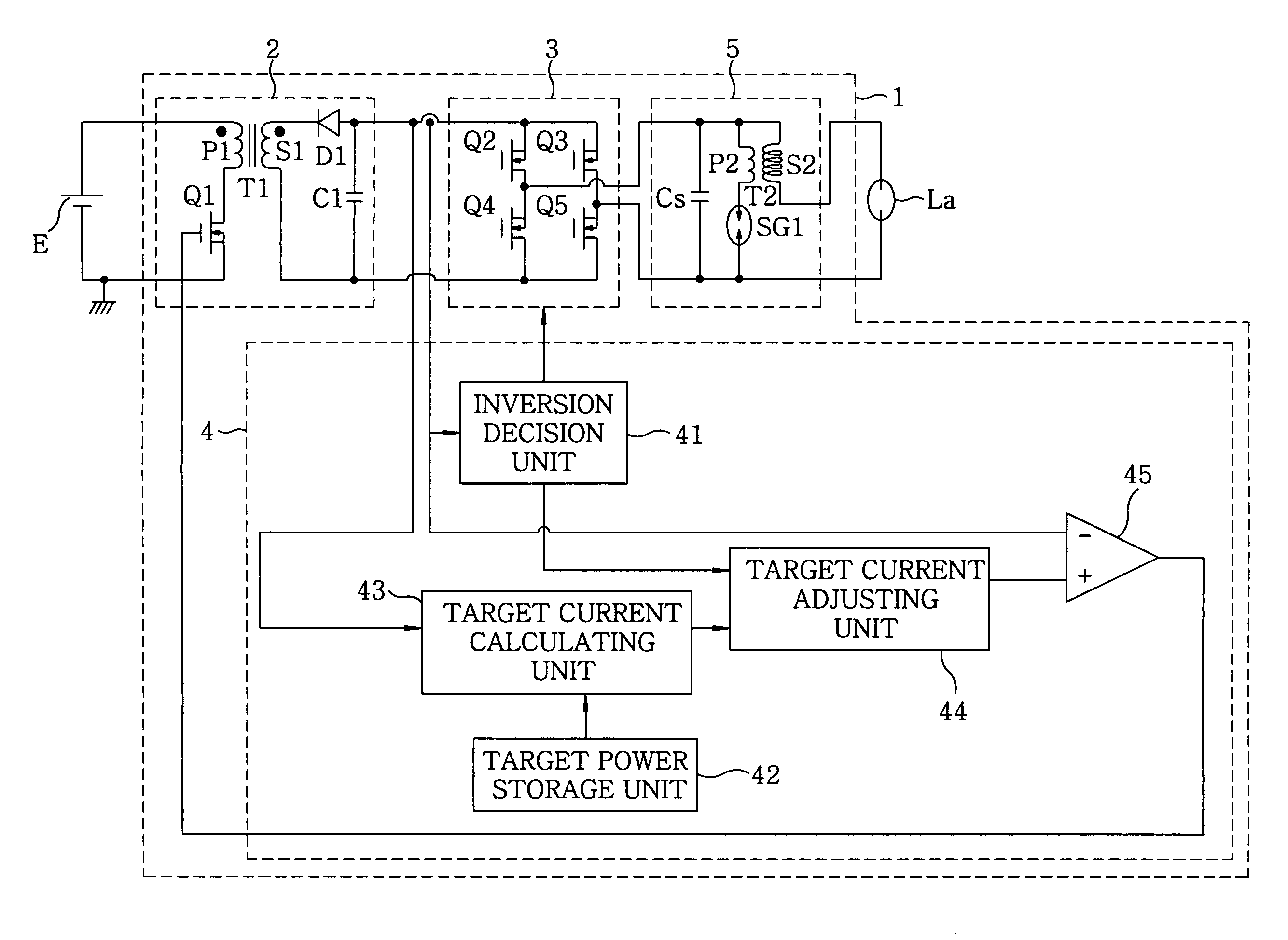
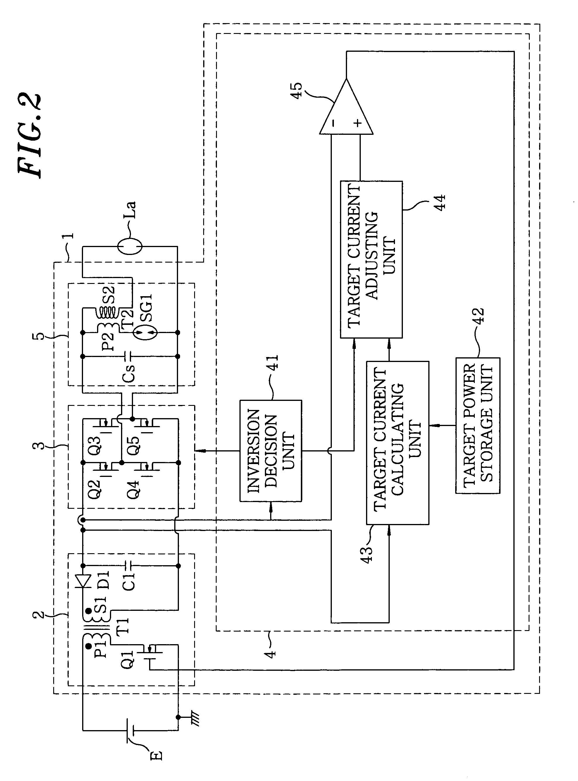
[0055]A discharge lamp lighting device 1 of this embodiment as shown in FIG. 2 includes a DC / DC converter 2 which serves as a DC power source for converting a voltage value of the DC power that is inputted from a DC power source E; an inverter 3 for alternating the polarity of the DC power that is outputted from the DC / DC converter 2 to output it to a discharge lamp La; and a controller 4 for controlling the DC / DC converter 2 and the inverter 3. Further, an igniter 5 is provided between the inverter 3 and the discharge lamp La to generate a high voltage for the start-up of the discharge lamp La.
[0056]To explain in detail, an output end on a low voltage side of the DC power source E is connected to ground, and the DC / DC converter 2 is a known flyback converter, which includes a transformer T1 having a primary coil P1 with one end connected to an output end on the high voltage side of the DC power source E while the other end is connected to the ground via a switching element Q1; an o...
second embodiment
[0088]The basic configuration of this embodiment is the same as the first embodiment, and therefore, illustration and explanation on those common parts will be omitted.
[0089]While the increment in the first embodiment has always been fixed to a certain value, the increment in this embodiment is allowed to vary, differing from the first embodiment.
[0090]For variation of the increment, for example, the increment during the elapsed time between 0 sec and 4 sec is maintained at a minimum value (0.2 A in FIG. 7, and 0 A in FIG. 9), and then the increment may gradually and linearly increase up to a maximum value, e.g., 0.4 A during the elapsed time between 4 sec and 50 sec. That is, during the power increasing period, the increment becomes less than that in the rated power period. For instance, in an example shown in FIG. 7, when the elapsed time is 4 sec, the increment becomes 0.2 A as shown in FIG. 8A; and when the elapsed time is 50 sec or more, the increment becomes 0.4 A as shown in ...
third embodiment
[0095]The basic configuration of this embodiment is the same as the first embodiment, and therefore, illustration and explanation on those common parts will be omitted.
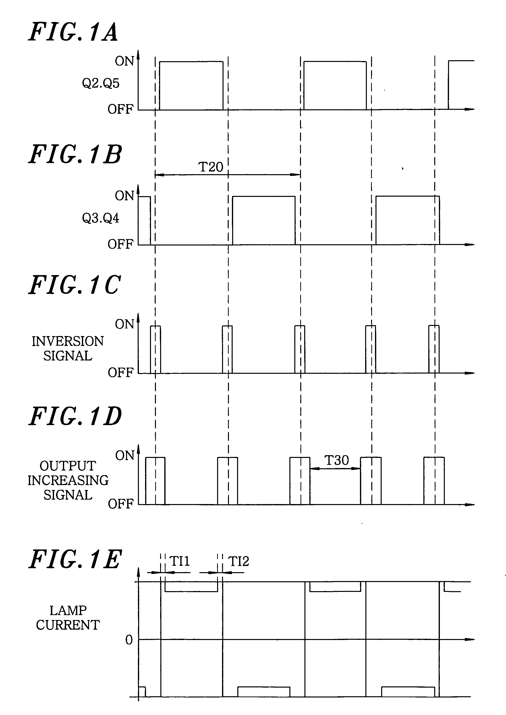
[0096]This embodiment differs from the first embodiment in that, in the first embodiment, the target current adjusting unit 44 adds the constant increment to the input target current value from the target current calculating unit 43 in the post and pre-inversion period TI1 and TI2 to increase a target current value, but in this embodiment, the target current adjusting unit 44 multiplies the input target current value from the target current calculating unit 43 by a multiplication factor not less than 1 to provided an increased target current value in the post and pre-inversion period TI1 and TI2. For instance, if the multiplication factor is 2, and the target current value in the rated power period is 2.6 A, the target current value in the post and pre-inversion period TI1 and TI2 would become 5.2 A as shown in FIG. 1...
PUM
 Abstract
Description
Claims
Application Information
 - R&D
- Intellectual Property
- Life Sciences
- Materials
- Tech Scout
- Unparalleled Data Quality
- Higher Quality Content
- 60% Fewer Hallucinations
Browse by: Latest US Patents, China's latest patents, Technical Efficacy Thesaurus, Application Domain, Technology Topic, Popular Technical Reports.
© 2025 PatSnap. All rights reserved.Legal|Privacy policy|Modern Slavery Act Transparency Statement|Sitemap|About US| Contact US: help@patsnap.com


