Discharge lamp lighting device, headlight device and vehicle having the same

a technology of lighting device and discharge lamp, which is applied in the direction of electric variable regulation, process and machine control, instruments, etc., can solve the problems of flickering or extinction of discharge lamps, generating electronic noise, shortening the life of discharge lamps

Active Publication Date: 2012-01-03
MATSUSHITA ELECTRIC WORKS LTD
View PDF3 Cites 2 Cited by
  • Summary
  • Abstract
  • Description
  • Claims
  • Application Information

AI Technical Summary

Benefits of technology

[0007]In view of the above, the present invention provides a discharge lamp lighting device which can minimize flickering and extinction phenomenon of the discharge lamp and reduce electronic noises while constraining electrical stress on the discharge lamp; a headlight device having the discharge lamp lighting device; and a vehicle equipped with the headlight device.
[0011]In accordance with the present invention, electrical stress upon the circuit components or the discharge lamp in the post-inversion period or in the pre-inversion period is restrained.

Problems solved by technology

In the above discharge lamp lighting device, when the polarity of the output from the inverter is inverted (hereinafter, referred to simply as“inversion”), the temperature of an electrode of the discharge lamp drops as the output current from the inverter to the discharge lamp is temporarily decreased to thereby make the discharge of the discharge lamp after inversion instable, thus causing flickering or extinction of the discharge lamp or generating electronic noises.
However, if the average value in one period of the output power is set too high, electrical stress upon the discharge lamp increases to thereby shorten the life span of the discharge lamp.

Method used


Image

  • Discharge lamp lighting device, headlight device and vehicle having the same
  • Discharge lamp lighting device, headlight device and vehicle having the same
  • Discharge lamp lighting device, headlight device and vehicle having the same

Examples


first embodiment

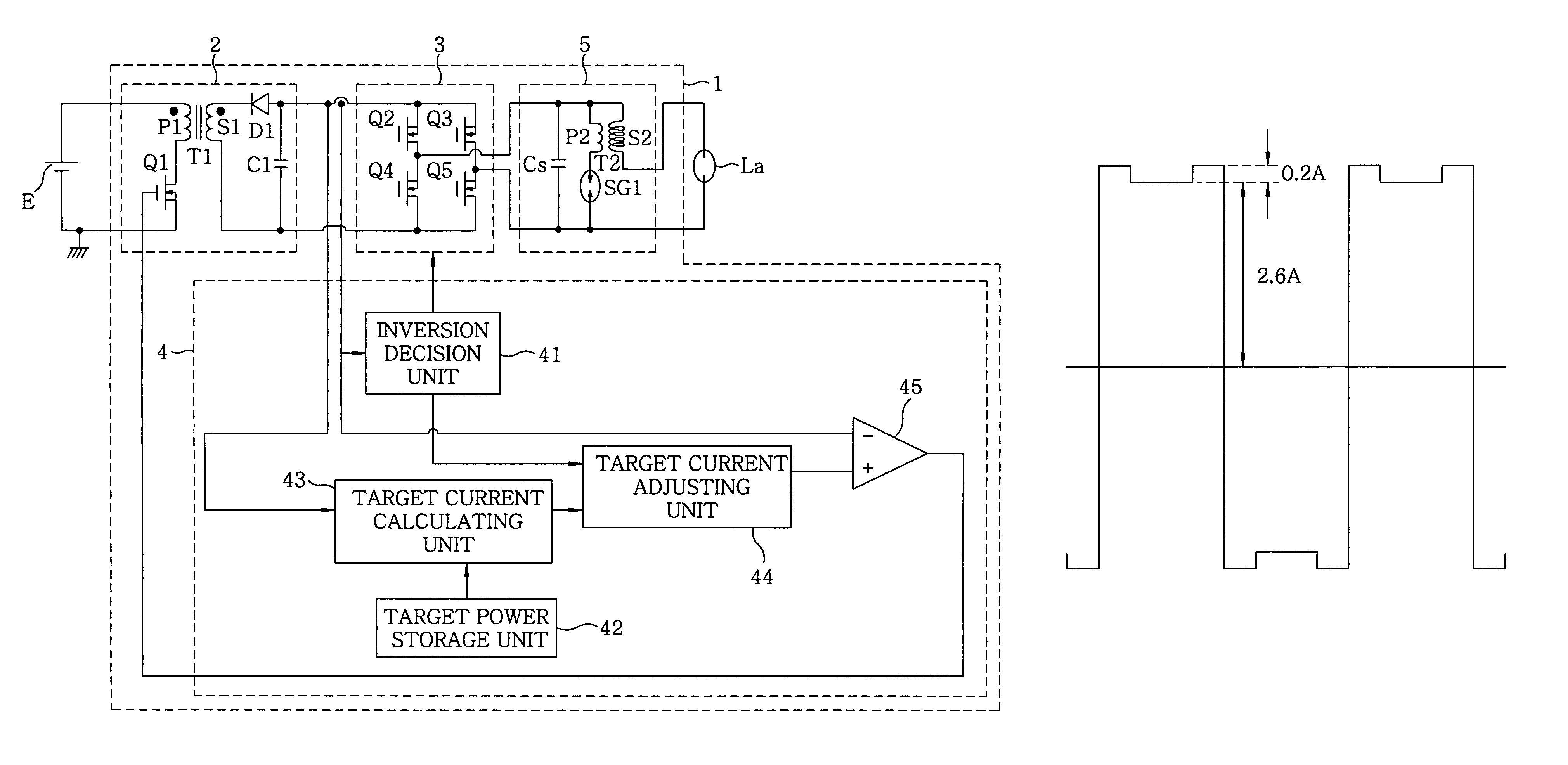
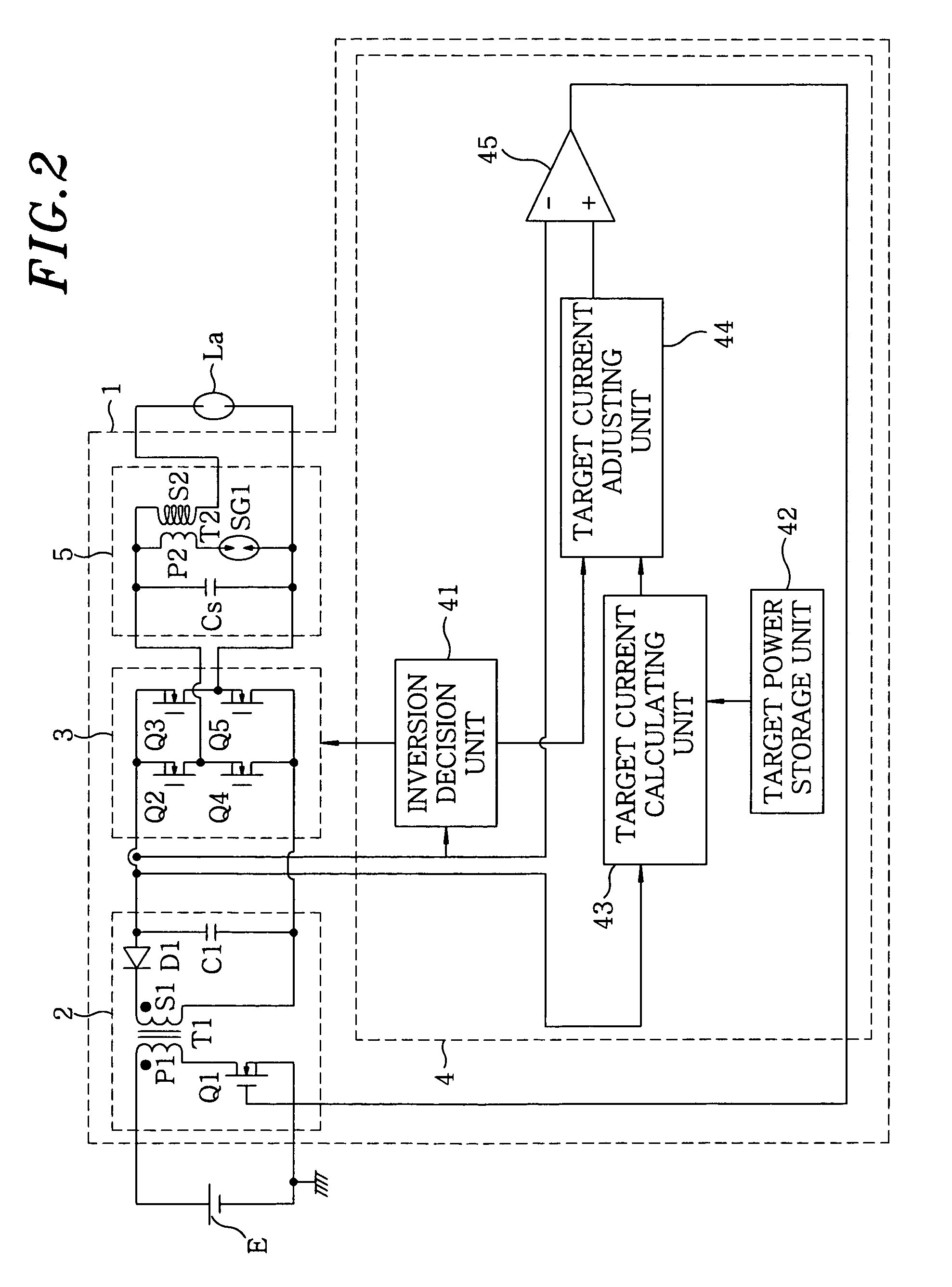
[0055]A discharge lamp lighting device 1 of this embodiment as shown in FIG. 2 includes a DC / DC converter 2 which serves as a DC power source for converting a voltage value of the DC power that is inputted from a DC power source E; an inverter 3 for alternating the polarity of the DC power that is outputted from the DC / DC converter 2 to output it to a discharge lamp La; and a controller 4 for controlling the DC / DC converter 2 and the inverter 3. Further, an igniter 5 is provided between the inverter 3 and the discharge lamp La to generate a high voltage for the start-up of the discharge lamp La.

[0056]To explain in detail, an output end on a low voltage side of the DC power source E is connected to ground, and the DC / DC converter 2 is a known flyback converter, which includes a transformer T1 having a primary coil P1 with one end connected to an output end on the high voltage side of the DC power source E while the other end is connected to the ground via a switching element Q1; an o...

second embodiment

[0088]The basic configuration of this embodiment is the same as the first embodiment, and therefore, illustration and explanation on those common parts will be omitted.

[0089]While the increment in the first embodiment has always been fixed to a certain value, the increment in this embodiment is allowed to vary, differing from the first embodiment.

[0090]For variation of the increment, for example, the increment during the elapsed time between 0 sec and 4 sec is maintained at a minimum value (0.2 A in FIG. 7, and 0 A in FIG. 9), and then the increment may gradually and linearly increase up to a maximum value, e.g., 0.4 A during the elapsed time between 4 sec and 50 sec. That is, during the power increasing period, the increment becomes less than that in the rated power period. For instance, in an example shown in FIG. 7, when the elapsed time is 4 sec, the increment becomes 0.2 A as shown in FIG. 8A; and when the elapsed time is 50 sec or more, the increment becomes 0.4 A as shown in ...

third embodiment

[0095]The basic configuration of this embodiment is the same as the first embodiment, and therefore, illustration and explanation on those common parts will be omitted.

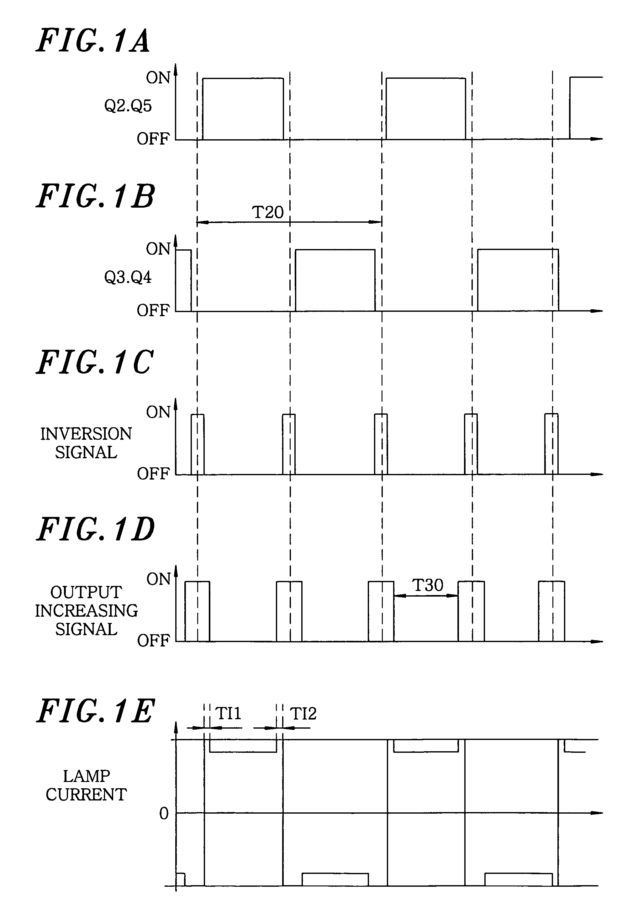
[0096]This embodiment differs from the first embodiment in that, in the first embodiment, the target current adjusting unit 44 adds the constant increment to the input target current value from the target current calculating unit 43 in the post and pre-inversion period TI1 and TI2 to increase a target current value, but in this embodiment, the target current adjusting unit 44 multiplies the input target current value from the target current calculating unit 43 by a multiplication factor not less than 1 to provided an increased target current value in the post and pre-inversion period TI1 and TI2. For instance, if the multiplication factor is 2, and the target current value in the rated power period is 2.6 A, the target current value in the post and pre-inversion period TI1 and TI2 would become 5.2 A as shown in FIG. 1...


PUM


Abstract

A discharge lamp lighting device includes: a DC power source; an inverter for inverting the DC power at a predetermined inversion time interval to supply a square wave AC power to a discharge lamp; and a controller for controlling the output power. The controller performs a synchronous operation and controls the DC power source such that DC power outputted during a period other than the output temporarily increasing period in a power increasing period is greater than the DC output power outputted during the period other than the output temporarily increasing period in a rated power period. Further, the controller controls the DC power source such that at least one of an increment of the output power for the output temporarily increasing period and a length of the output temporarily increasing period is less in at least a part of the output increasing period than in the rated power period.

Description

FIELD OF THE INVENTION[0001]The present invention relates to a discharge lamp lighting device, a headlight device and a vehicle equipped with same.BACKGROUND OF THE INVENTION[0002]Traditionally, a discharge lamp lighting device for lighting high pressure discharge lamps such as metal halide lamps or the like. Such a discharge lamp lighting device employs a square wave lighting technique to avoid an acoustic resonance phenomenon and has been used for lighting the light sources of, e.g., a spotlight, a projector and the headlight device of a vehicle.[0003]This kind of discharge lamp lighting device has a DC power source which outputs a DC power, and an inverter which inverts the polarity of the DC power outputted from the DC power source at a predetermined inversion time interval to thereby obtain a square wave AC power and then supplies the square wave AC power to a discharge lamp.[0004]In the above discharge lamp lighting device, when the polarity of the output from the inverter is ...

Claims


Application Information

Patent Timeline
Patent Type & Authority Patents(United States)
IPC IPC(8): H05B37/02
CPCH05B41/2882H05B41/2928
Inventor TANAKA, TOSHIFUMIKONISHI, HIROFUMIUKEGAWA, SHINANAMI, SHINICHISEKI, MASAHIRO
Owner MATSUSHITA ELECTRIC WORKS LTD
Why Eureka
Try Eureka