Face Panel for a Computer Housing

a computer housing and face panel technology, applied in computing, electrical apparatus casings/cabinets/drawers, instruments, etc., can solve the problems of inconvenient user re-assembling, inability to remove the cover front side, inability to re-assemble the cover, etc., and achieve the effect of quick and convenient removal

Inactive Publication Date: 2010-03-04
AOPEN
View PDF23 Cites 2 Cited by
  • Summary
  • Abstract
  • Description
  • Claims
  • Application Information

AI Technical Summary

Benefits of technology

[0008]Therefore, the main object of the present invention is to provide a face panel for a computer housing. The face panel has a cover plate assembly that can be quickly and conveniently assembled to or disassembled from a face panel body.
[0019]In the face panel for a computer housing according to this invention, with the arrangement of the cover plate assembly, the user can use only one finger or two fingers to press the press portion(s) of the slide block(s) to release the locked state between the cover plate assembly and the face panel body. Thus, the cover plate assembly can be quickly and conveniently removed from the front side of the face panel body. In addition, by using the resilient connecting portions to restore the second engaging hooks or the engaging hooks to an engaged position, the cover plate assembly is switchable between locked and unlocked states with respect to the face panel body.

Problems solved by technology

The removal operation cannot be conducted from a front side of the face panel body 11, which is inconvenient for the user during removal.
Furthermore, if a force is improperly applied by the user during removal of the covers 12, breaking of the engaging hooks 122 may occur, thereby rendering it impossible to re-assemble the covers 12 to the face panel body 11.

Method used


Image

  • Face Panel for a Computer Housing
  • Face Panel for a Computer Housing
  • Face Panel for a Computer Housing

Examples


Embodiment Construction

[0035]Through a detailed description of the preferred embodiments, the technical means adopted to achieve the intended object and advantageous effects of the present invention should be better understood. However, the accompanying drawings are provided for reference and illustration only and should not be based upon to limit the scope of protection sought for the present invention.

[0036]Before the present invention is described in greater detail, it should be noted that like elements are denoted by the same reference numerals throughout the disclosure.

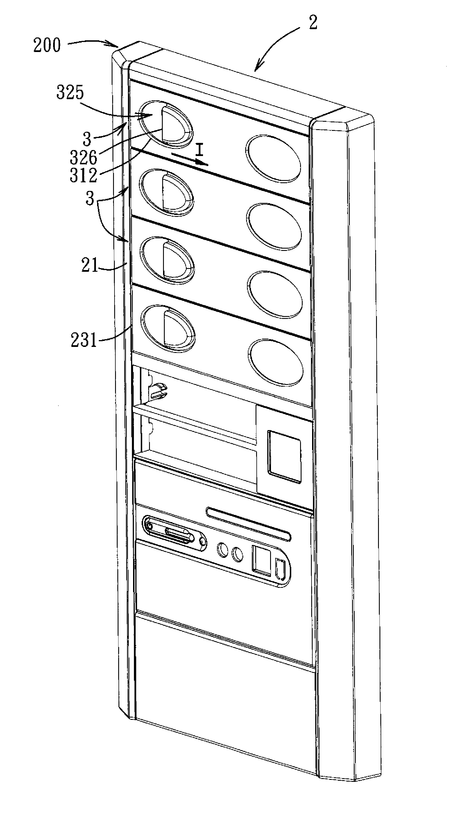
[0037]Referring to FIG. 4, the first preferred embodiment of a face panel 200 for a computer housing according to the present invention is shown to include a face panel body 2 and a plurality of cover plate assemblies 3 removably assembled to the face panel body 2. Since the cover plate assemblies 3 are identical in structure, to facilitate description and for the sake of clarity, the cover plate assemblies 3, and component parts there...


PUM


Abstract

A face panel for a computer housing includes a face panel body and a cover plate assembly. The face panel body includes a surrounding wall having first and second engaging grooves, and a mounting hole. The cover plate assembly is provided in the mounting hole and is assembled to the surrounding wall, and includes a cover plate having a through hole and a first engaging hook for engaging the first engaging groove, and a locking member having a fixed block coupled to the cover plate, a slide block, and a resilient connecting portion interconnecting the fixed and slide blocks to provide the slide block with a restoring force. The slide block includes a second engaging hook for engaging the second engaging groove, and a press portion exposed through the through hole and pressible to enable the second engaging hook to disengage from the second engaging groove.

Description

CROSS-REFERENCE TO RELATED APPLICATION[0001]This application claims priority of Taiwanese Application No. 097215319, filed on Aug. 26, 2008.BACKGROUND OF THE INVENTION[0002]1. Field of the Invention[0003]The invention relates to a face panel for a computer housing, more particularly to a face panel for a computer housing which has a mounting hole for insertion of a data access device and which permits a cover plate assembly to be mounted in the mounting hole.[0004]2. Description of the Related Art[0005]Referring to FIGS. 1, 2, and 3, a face panel 1 of a conventional computer housing includes a face panel body 11, and a plurality of covers 12 removably assembled to the face panel body 11. The face panel body 11 includes an upright wall 111, a mounting hole 113 formed in the upright wall 111, and a surrounding wall 112 projecting rearwardly from the upright wall 111 and defining the mounting hole 113. The surrounding wall 112 is for mounting of data access devices, such as an optical ...

Claims


Application Information

Patent Timeline
Patent Type & Authority Applications(United States)
IPC IPC(8): H05K7/00
CPCG06F1/181
Inventor WANG, JO-CHIAO
Owner AOPEN
Why Eureka
Try Eureka