Apparatus for shooting a nail

a nail and nail technology, applied in the field of nail accessories, can solve the problems of inability to replace a different type of barrel to meet different applications, difficult to eliminate malfunctions, and inability to ensure the proper centering of the piston rod when shooting nails, etc., to achieve convenient and fast removal and facilitate the replacement of the barrel.

Inactive Publication Date: 2012-09-25
SUN GRACE HLDG
View PDF16 Cites 0 Cited by
  • Summary
  • Abstract
  • Description
  • Claims
  • Application Information

AI Technical Summary

Benefits of technology

[0020]According to the apparatus for shooting a nail of one aspect of the present invention, the barrel may be removed conveniently and quickly as desired to facilitate the replacement of the barrel for different application or removal of the nail blocked in the apparatus for shooting a nail.
[0021]According to the apparatus for shooting a nail of another aspect of the present invention, it is ensured that the piston rod is concentric with the barrel when hitting the nail and the hit force of the piston rod will not lose.

Problems solved by technology

It is usually difficult to eliminate a malfunction if the nail is blocked in the barrel.
Moreover, it is impossible to replace a different type of barrel to meet different applications.
The conventional apparatus for shooting a nail can not always ensure that the piston rod is properly centered during its movement.

Method used


Image

  • Apparatus for shooting a nail
  • Apparatus for shooting a nail
  • Apparatus for shooting a nail

Examples


Embodiment Construction

[0030]The apparatus for shooting a nail according to the present invention will be explained in detail below with reference to the accompany figures. Only the main components of the apparatus for shooting a nail according to the present invention are shown in the figures while some known components such as a trigger mechanism are not shown.

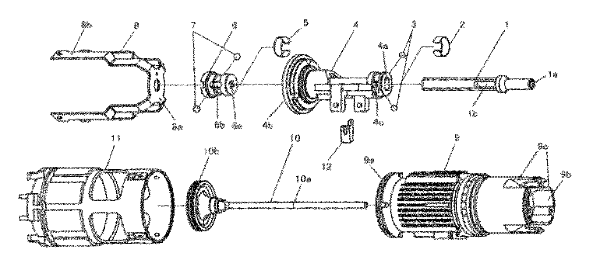
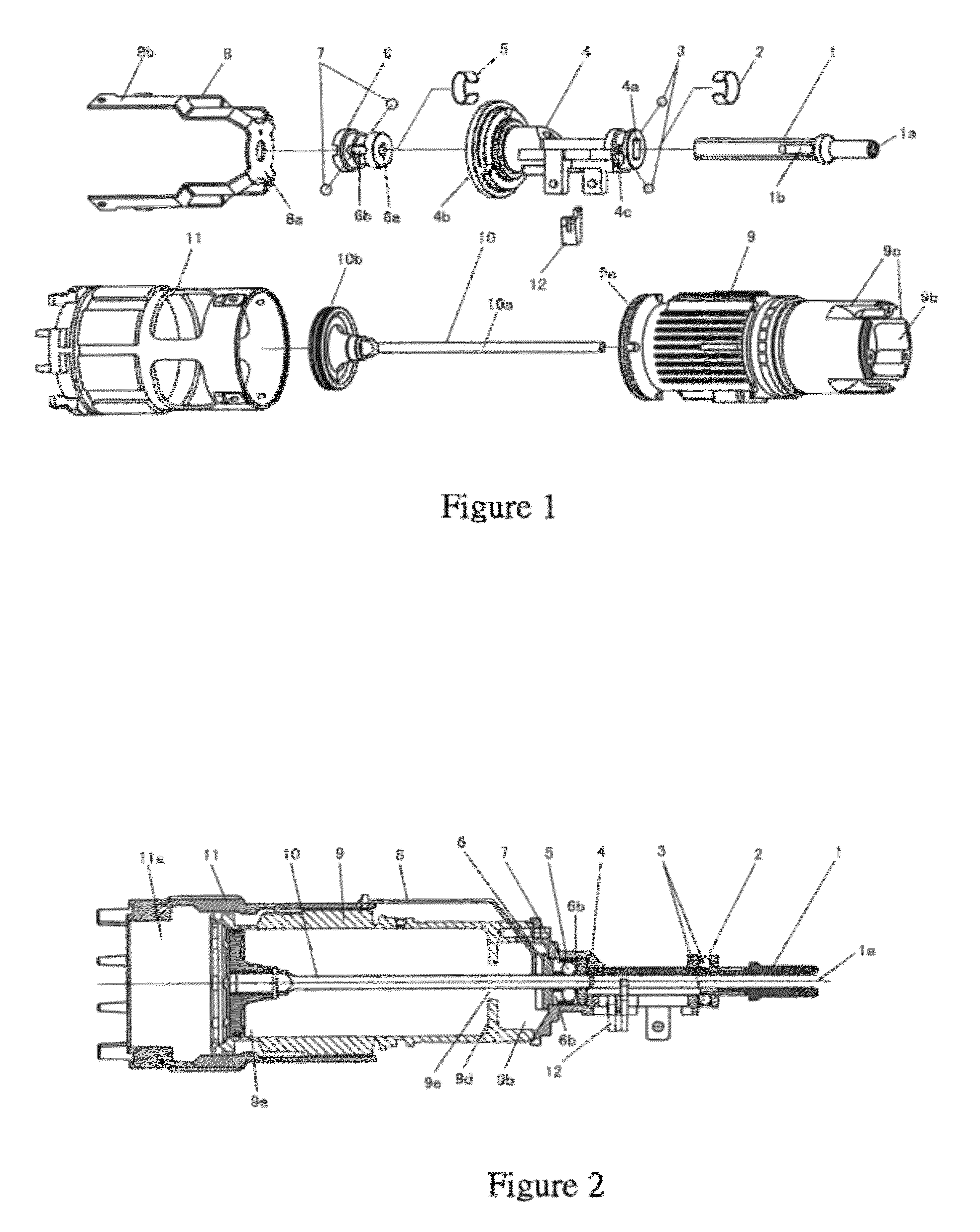
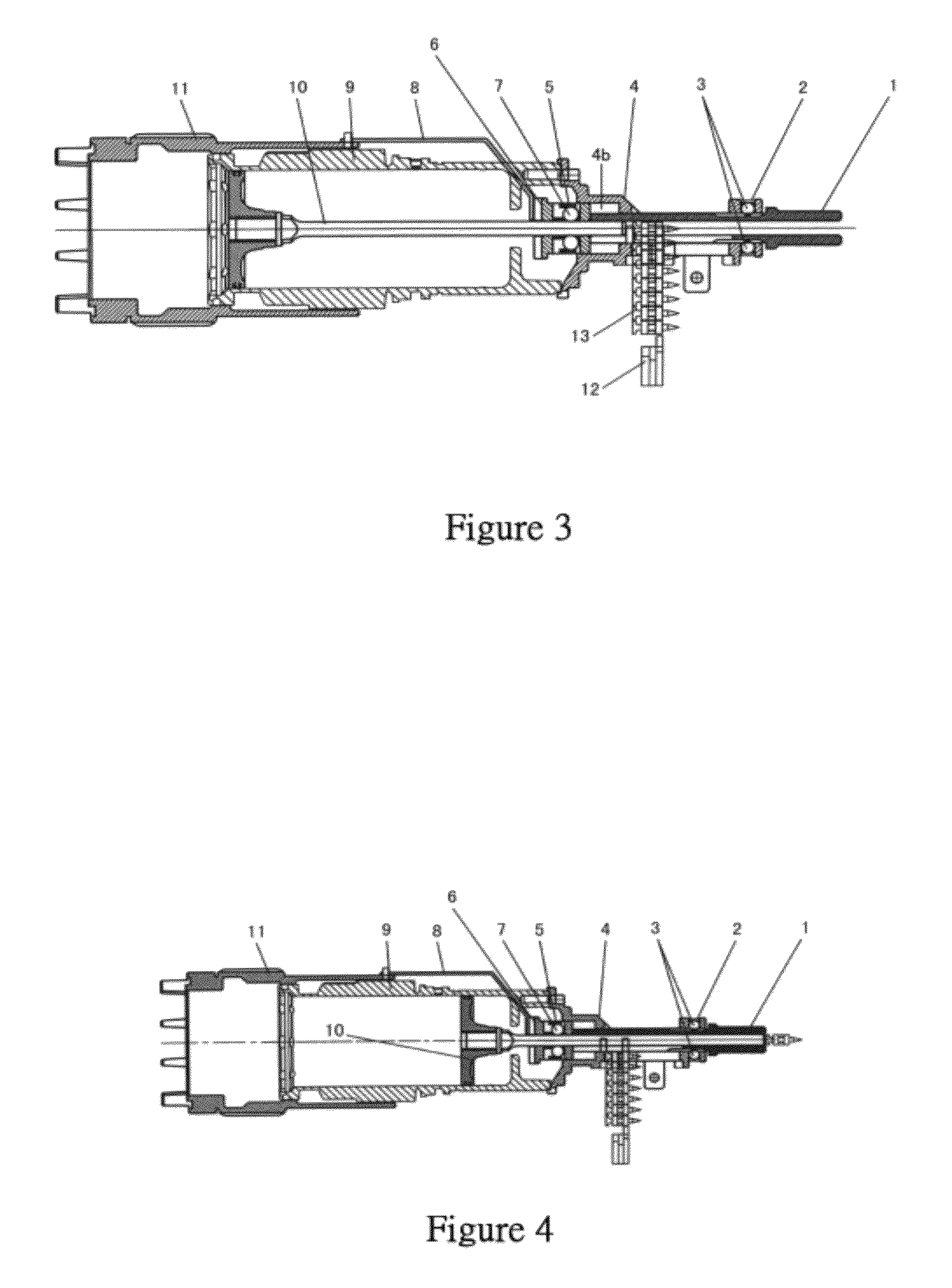
[0031]Referring to FIGS. 1, 2, 7 and 8, the apparatus for shooting a nail according to the present invention generally comprises a barrel 1, a barrel support 4, a centering sleeve 6, a link frame 8, a cylinder 9, a piston rod 10 and an outer housing 11.

[0032]A first receiving portion 4a for receiving the barrel 1 and a second receiving portion 4b for receiving the centering sleeve 6 and communicating with the first receiving portion 4a are formed within a body of the barrel support 4. The barrel 1 and the centering sleeve 6 are movably mounted in the barrel support 4. A through hole 6a is formed through a body of the centering sleeve 6. The link f...


PUM


Abstract

The present invention provides an apparatus for shooting a nail comprising a barrel, a barrel support, a centering sleeve, a link frame, a cylinder, a piston rod and an outer housing, wherein the barrel is mounted removably in the barrel support. As desired, the barrel may be removed conveniently to facilitate the replacement of the barrel for different application or removal of the nail blocked in the apparatus for shooting a nail. Furthermore, at least two longitudinally elongated slots may be formed in the centering sleeve and penetrate through the wall of the centering sleeve, the steel balls received in the slots are held in the slots via a snap ring so as to embrace the rod body of the piston rod. Therefore, it is ensured that the piston rod is concentric with the barrel when hitting the nail and the hit force of the piston rod will not lose.

Description

FIELD OF THE INVENTION[0001]The present invention relates to an apparatus for shooting a nail.BACKGROUND OF THE INVENTION[0002]An apparatus for shooting a nail is used widely in the construction industry. The apparatus for shooting a nail pushes a piston rod forwards by means of explosive force of a gunpowder or thrust of a compressed gas such that the piston rod boosts and shoots a nail from a nail feeder along a barrel. As a result, the nail is shot into a desired location.[0003]In the conventional apparatus for shooting a nail, the barrel is fixedly mounted. It is usually difficult to eliminate a malfunction if the nail is blocked in the barrel. Moreover, it is impossible to replace a different type of barrel to meet different applications. Furthermore, to shoot the nail into a proper location, it is necessary to ensure that the piston rod is properly centered during its movement. The conventional apparatus for shooting a nail can not always ensure that the piston rod is properly...

Claims


Application Information

Patent Timeline
Patent Type & Authority Patents(United States)
IPC IPC(8): B27F7/02
CPCB25C1/08
Inventor CHEUNG, HON KAN
Owner SUN GRACE HLDG
Why Eureka
Try Eureka